Dangers Associated with Passive Ground Fault Protection and Detection
As power generation evolves around the world to meet demand, more smart grids require the storage of excess generated electricity to maximize peak efficiency. Battery storage systems are becoming more widely used. In order to help today's smart grids operate, smart electrical safety equipment is a must. Proper electrical safety doesn't just protect personnel - it helps protect  equipment from electrical and fire damage.
For decades, electrical systems classified as critical infrastructure have utilized ungrounded and high-resistance grounded substations. In a single ground fault condition, these system configurations allow processes to continue to operate. In North America, passive three-light bulb indicator systems have been used for many years for ground-fault detection.
While NEC 250.21 (B) permits the use of three-light systems for detection, it should be noted that the NEC is a minimum design standard; ground-fault detection, location and protection technology has advanced significantly in the last 20 years. Since these passive systems are still used, however, it's important discuss how they work and the typical issues that arise, especially when incorporating newly designed energy storage systems into existing Ungrounded, or High Resistance Grounded substations or facilities.
System Description:
- Passive grounds fault detection systems are designed for operation on three-phase ungrounded, or high-resistance grounded systems. These devices will not work on any type of solidly grounded system.
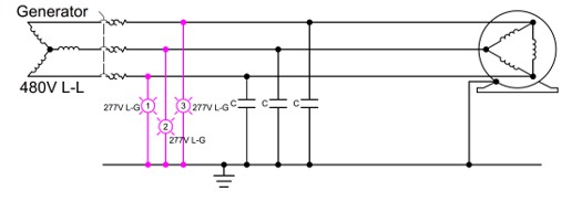
- A traditional three-light ground fault detection system is wired in a "wye" configuration, with the center of the wye connected to ground, rated at the full voltage of the system. For example, a 480-V System requires 480-V pilot lights (which may include potential transformers).
(on the left is a typical "Three-Light" System)
System Operation:
- According to a study conducted by Rockwell Automation, in normal operation, all three lights will be at approximately 57% brightness.
- When one phase of the power system is faulted to ground, the light connected to the faulted phase will be off. The other two lights will be at full brightness.

For example:
- On a three-phase 480-V system with no ground fault, phase-to-ground voltage is 277 V on each phase.
- If Phase 1 (Figure 1) were to experience a ground fault, the phase-to-ground voltage on L1 would be 0 V.
- The voltage to ground on L2 and L3 would be 480 V.
- If the ground fault was not a "solid" fault, but had some type of impedance (such as in a motor winding), one light would be dim, and the other two would be brighter.
System Advantages / Disadvantages:
- A single three-light detector on an electrical system only indicates if a fault is present and in the faulted phase. It cannot help in locating the source of ground fault(s).
- The three lights are blind to symmetrical faults (two high-impedance faults) on a system. This can lead to a catastrophic situation, with very difficult-to-locate ground faults.
- Since they have no means of communication, this type of system does not typically notify personnel there is a fault on the system. In this case, fault indication is only provided when a technician observes the lights. With the shortage of manpower in most facilities, this could result in undetected ground faults on a system for extended times.
- If a ground fault is allowed to remain on a system for an extended period, there is risk that the ground fault could escalate to a phase-ground-phase (or phase-phase) fault, resulting in catastrophic equipment failure. This can occur when a second ground fault occurs on a system. This could present an arc flash hazard, especially if the second fault was caused by personnel contact.
Note: The Industrial Power System Grounding Design Handbook states that 95% of all electrical faults are phase-to-ground faults. IEEE141-1993 Recommended Practice for Electric Power Distribution for Industrial Plants 7.2.2 states "there is no arc flash hazard (on HRG systems) as there is with solidly grounded systems, since the current is limited to approximately 5amps."
Recommendations:
Solutions to these issues come in many forms. Conversion to high resistance grounding with individual feeder protection is often selected, to help alleviate the transient overvoltage potential inherent to ungrounded systems, and to make it easier to locate ground faults.
Where ungrounded systems are still utilized, insulation monitoring devices can provide critical infrastructure system-to-ground resistance monitoring to detect ground faults, and even to allow location of faults while maintaining continuity of service.
As more energy storage applications are being retrofitted into existing systems, safety and reliability of both the energy storage module and the end-user's electrical system must be considered. Failing to do this undermines any advantages of energy storage. These best practice principles should begin during the specification stage of a project - not after a system has been deployed.
Dale Boyd has a Bachelor of Science degree in Electrical Engineering Technology degree from Old Dominion University. He spent the first (14) years in the Pulp & Paper Industry as a Project Design Engineer, and spent several years as Chairman of the Global Power Committee for a major consumer products paper company. He has also worked with various electrical manufacturers; his roles have included power consulting, national accounts manager and regional sales director. Dale is a member of IEEE, and active in the pulp & paper IEEE Group. He has developed power system solutions with many end customers, ranging from electrical distribution system upgrades to ground-fault solutions.
BENDER provides electrical safety equipment to industries worldwide, ensuring that people, equipment, and facilities worldwide are protected with the latest in electrical safety technology.
Bender | www.bender.org
Volume: 2018 July/August


