


Outside Framed Wind Turbine Improved


The latest design from Lux Wind Power uses a frame on the outside of the Vertical Axis Wind turbine (VAWT) instead of using guy cables or a mast fixed to the earth. Normally, long beams with a small cross section requires bracing from several directions for most applications, though this is not neccesarily the case.
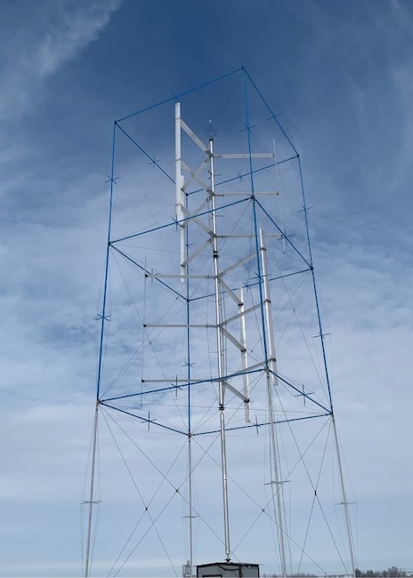
The drawing above shows 2 separate turbines, one on top of the other. The 3 outside frames are cubic shapes and are also stacked on top of each other. The turbines are slightly smaller than the cubic frame to allow for movement in high winds. Most straight bladed VAWT have Height/Diameter ratio close to one — the cube shape is for simplicity. Each cube has 4 vertical beams, 4 horizontal beams and 5 pairs of diagonal beams crossing in the middle of each side. The diagonal beams are tensioned, which causes the other beams to be in compression, even under extreme wind loads. A turbine in the bottom cube may be added even if it is not the full height of the cube. The diameter of the lower turbines could be a bit smaller than the top turbine to accommodate wind shear.
The diagonal beams/cables on the top face of each cube contain a bearing housing and bearing at the intersection. The bearings and housings are the only places where the outside frame experiences the thrust forces from the wind.
The weight of all the masts, struts and blades is supported by the bearing at the bottom of the lowest mast. Therefore, the only major forces acting on the cubed frame are the thrust forces from the wind on each turbine and gravity from the frame above it. The ends of the horizontal and vertical beams can be considered as pinned, which prevents bending moments, torsion or shear on these beams. All beams are in compression, so column buckling is the only mode of concern.
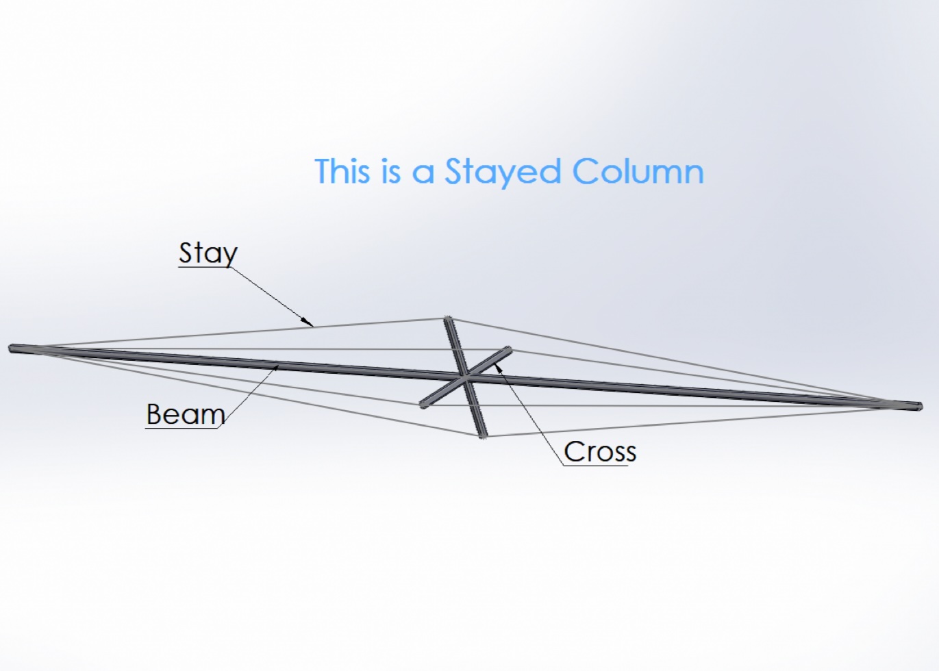
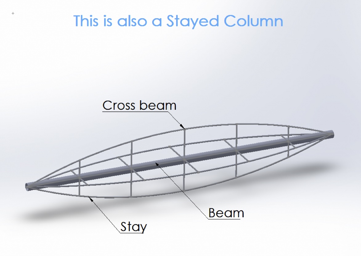
There are many ways to change the maximum allowable force on stayed columns. Adjusting any of the properties such as the cross section or lengths of the main beam, crosses or stays causes the Pcr to change. Making changes to the PSSC may increase Pcr but it may also increase the weight to the point where the change is not economically feasible. The PSSC was analyzed using a numerical procedure called the Stiffness Probe Method developed by German Gurfinkel and Sudarshan Krishnan.
Gravity becomes a bigger concern when the beams are in a horizontal position. However, the tension in the stays below the beam can be increased to overcome the gravity force and to keep the beams straight. These stays typically need to have a larger cross section due to the increased tension.
The crosses and stays on the beams do not interfere with the blades and the parasitic drag from the wind is minimal. The horizontal diagonals are positioned between the upper and lower turbine blades, which require a clearance to allow for movement within the cubed frame. The frame is secured in position on the ground by 4 pillars/posts at each corner extending above the ground at a favourable height.
This is an excellent way to support a floating wind turbine for offshore energy. The four corners of the frame are a considerable distance apart, which helps to stabilize any structure floating on the ocean. The frame could be continued at and below water level, providing a base for the mechanical components while lowering the center of gravity.
Lux Wind Power | https://www.luxwindpower.com/