


Making Ground Work


Foundations for wind turbines and transmission lines normally consist of large, reinforced concrete spread footings. Compression loads on soil are only supported by the soil; overturning loads are resisted by the counterweight provided by the concrete foundation. The changes in loading from compression to uplift can cause a fatigue problem, which is difficult to predetermine. Consequently, overturning of the wind turbine may result (Figure 2).
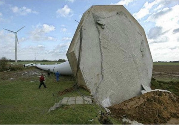
Overturning failure caused by massive rainstorms
For foundations on soil, an alternative post-tensioned foundation system was developed using micro piles supporting a smaller foundation-pile cap. Not only does this micro pile system minimize, or eliminate, the fatigue problem, but it can also provide a total foundation cost savings of about 25 percent (75 percent smaller foundation area, 40 percent less in concrete, 70 percent less reinforcing steel).
Design Objectives
- Achieve a design load in compression and/or tension with the required factor of safety.
- Provide a rigid foundation.
- Improve rotational stiffness and reduce movement of the foundation.
- Reduce excavation and backfill required for the pile cap/tower foundation.
- Require only small drilling equipment.
- Reduce consumption of materials to optimize foundation efficiency and performance.
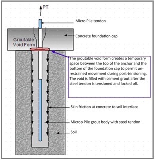
A groutable void form (GVF) temporarily separates the pile from the pile cap during stressing and testing to a load higher than the design load in compression and tension, while also allowing for some range of pile movement. After post-tensioning, the GVF is filled with cement grout to also transfer compression loads to the pile.
Prime Advantages
- Controls foundation settlement and prevents overloading the soil (bearing capacity failure) with a prescribed sequence of post-tensioning.
- Post-Tensioning in balanced anchor groups permits gradual load transfer into the piles, without overstressing the soil.
- Settlement of the foundation cap is minimized as the piles take over the compression load from the cap.
- Fatigue failures can be eliminated since the post-tensioned tension and compression loads are higher than the design loads and, as such, minimize or eliminate movements during load changes.
- Reduction of concrete and steel lessens environmental impact.
Load transfer diagram
Method 1 - Micro piles are installed prior to placing the concrete foundation cap.
A foundation for a 1.6 MW wind turbine was constructed in Tehachapi, California, using 300mm diameter pre-drilled post-tensioned micro piles and GVFs. The 100m tall lattice tower was founded on five individual pile caps, each supported by 4 micro piles. The post-tensioned micro pile/GVF system was load tested to provide assurance that the construction cost and long-term maintenance of the micro pile system could be reduced.
Method 2 - Micro piles are installed after placing the concrete foundation cap.
The advantage of the second method is that the micro piles are drilled through pre-formed sleeved holes in the foundation cap fitted with a pre-installed GVF under the foundation cap.
The disadvantage is that the drill hole size is determined by the smaller sleeve, inside the foundation slab, which does not provide sufficient cement grout body under the GVF. The smaller sleeve size is dictated by the size of the bearing plate for the micro pile.
When using the grout injection bored method with hollow bars, however, the cement grout is injected simultaneously during the drilling operation. The drill bit has small diameter side holes through which the grout will exit under high pressure, as during jet grouting. This will flush and create a larger size drill hole than the drill bit size under the GFV, creating a sufficient cement grout body underneath the GVF. This also improves the condition of the ground around the micro pile, and creates a higher skin friction capacity.
Stressing of the micro piles simultaneously, in pairs, will pre-stress the piles and post-tension the foundation before the GVF is filled with cement grout.
The number of Micro Piles stressed in pairs is dictated by the compression load capacity of the soil. When this load is reached, the GVFs are grouted. After the grout has reached sufficient strength, the stressing procedure can continue.
Wind turbine and foundations composed of post-tensioned Micro Piles with GVFs improves safety and lowers cost, making this system a competitive alternative to large reinforced concrete and large mono-pipe pile foundations on soil.
Horst Aschenbroich, Dipl. Ing. Is the Owner/President of Con-Tech Systems, an innovator and supplier of geo-support solutions and construction technology systems in North America.
Con-Tech Systems | contechsystems.com
Author: Horst Aschenbroich, Dipl. Ing.
Volume: 2023 May/June