

Cracking Under Stress: What causes blade bearing cracks, and where to find them before it’s too late


Pitch bearings, also known as blade bearings, connect the wind turbine blade root to the turbine rotor hub. The blade bearings allow the blade position to be optimized at various stages of operation. This includes optimized angle of attack to control drivetrain load, usually to maximize output. In other words, properly functioning pitch bearings are critical to maximize productivity of wind tubine generators (WTGs).
In recent years, the occurrence of cracking rings on blade bearings has been increasing. In our efforts to understand what is causing this problem we have inspected many failed bearings, as well as discussed with operators, consultants, and manufacturers worldwide.
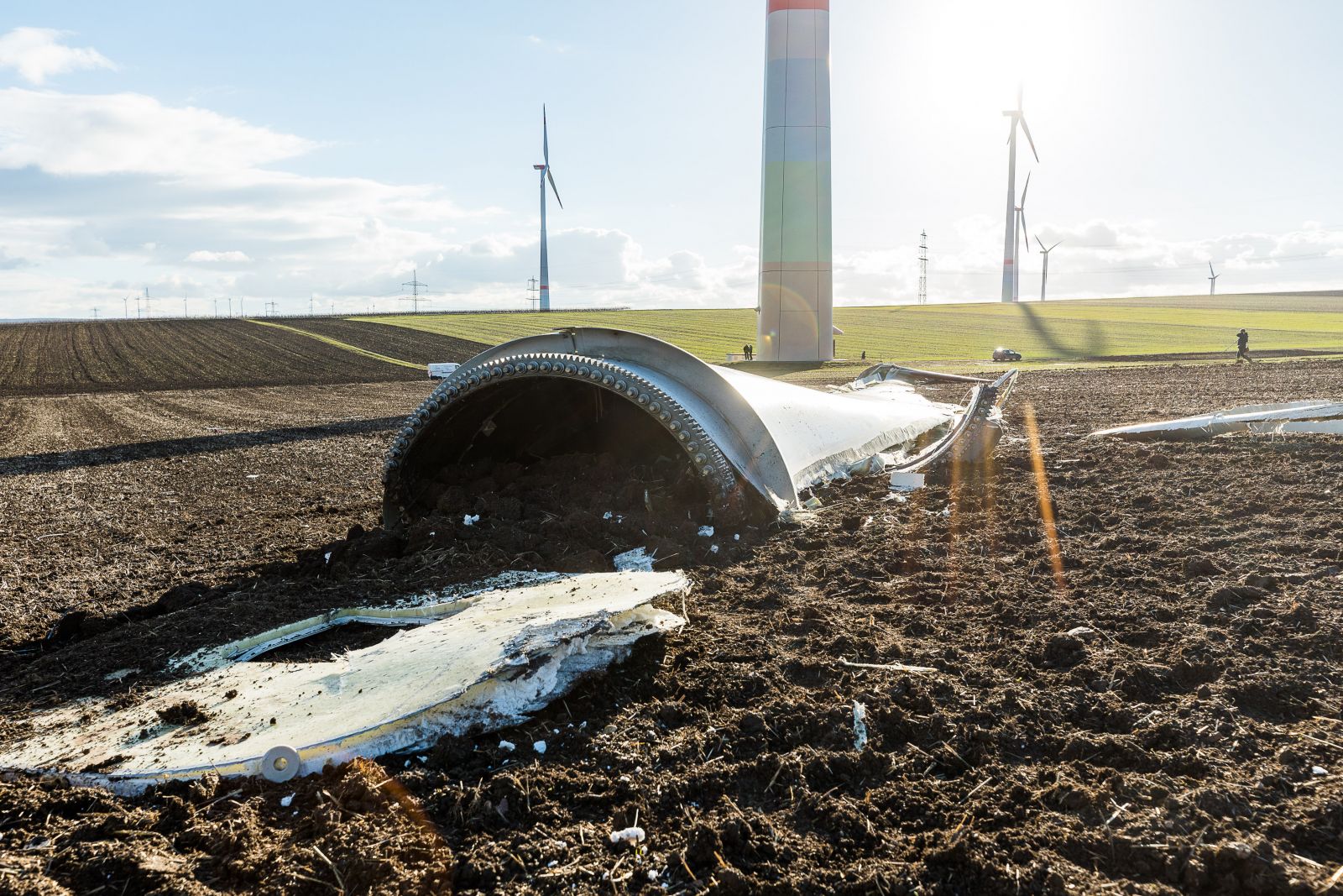
(Photo credit: Carsten Selak)
Root causes of cracking rings
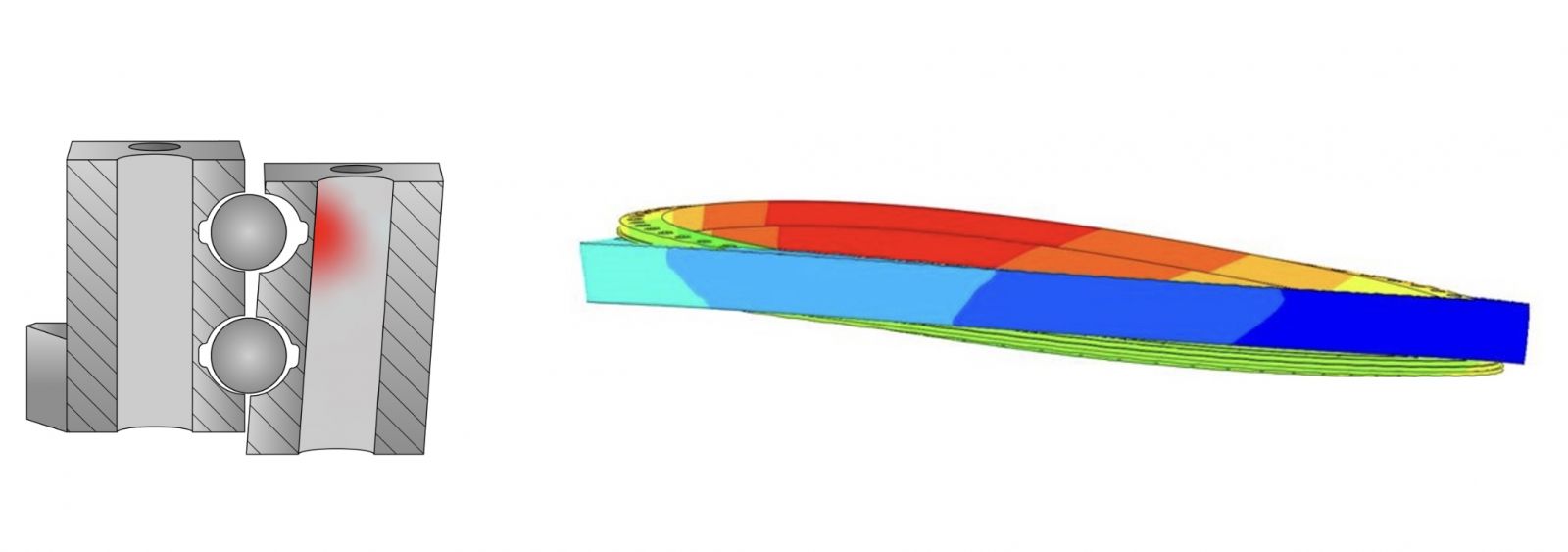
.jpg) At the core of the failure is the combination of bearing design and the structure it is attached to. The bearing consists of 2 rows of balls with a 45 degree preloaded contact angle. When a moment load is applied to this bearing, from either aerodynamic thrust load or gravity bending, the 45-degree contact angle resolves these forces into axial and radial components ( fig 1 at right). The roller and raceway system is capable of carrying these loads, but requires an attached structure that can resist substantial deformation of the bearing from this loading. If the bearing is allowed to deform, it will no longer be able to live its full intended service life.
At the core of the failure is the combination of bearing design and the structure it is attached to. The bearing consists of 2 rows of balls with a 45 degree preloaded contact angle. When a moment load is applied to this bearing, from either aerodynamic thrust load or gravity bending, the 45-degree contact angle resolves these forces into axial and radial components ( fig 1 at right). The roller and raceway system is capable of carrying these loads, but requires an attached structure that can resist substantial deformation of the bearing from this loading. If the bearing is allowed to deform, it will no longer be able to live its full intended service life.
When this bearing type is highly loaded in a pitch application, the highest stress concentration occurs within the bolt holes on the outer ring, just behind the outboard raceway (figure 2 below left). When the bearing is allowed to deform under load (figure 3 below right), this emphasizes this stress concentration.
The blade bearing application in a wind turbine accumulates load cycles quickly. A turbine that turns 12rpm, will rotate 17,280 revolutions every day, 24/7. Every time a blade goes through the 12 o’clock and 6 o’clock positions, the gravity bending moment changes direction (2 times per revolution). The blade bearings on this turbine could accumulate up to 34,560 cycles per day, and up to 12.6 million cycles per year!
Inspection of cracked bearings
Once the cracked face is exposed, it is easy to see the beach marks, which are a classic indicator of fatigue driven by load cycling. These beach marks can be traced back to a central point (figure 4 below). This central point is the initiation point of the crack.
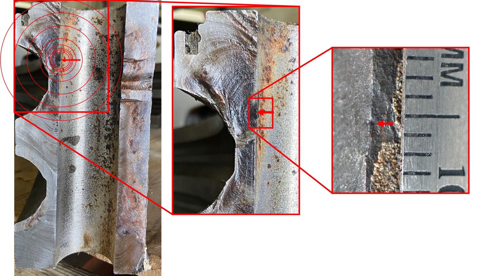
In all the inspections we have performed on cracked bearings, this initiation point has been found in the same place: in the bolt hole, just behind the blade side raceway. This is the same place that we already know will have the highest concentration of stress.
In the early days of the wind industry, there were some applications and some sites with cracking failures, but they remained somewhat isolated; they were largely attributed to poor protection of the bolt holes, combined with long transportation or laydown periods. This allowed corrosion to form inside of the bolt holes, further exacerbating the stress concentration described above. These were addressed with better care and corrosion protection during production.
In the last few years, we have seen the cracking ring failure mode start to increase, especially on turbines with 100m and larger rotor diameters. In some cases, corrosion pits as small as 250µm are found at the initiation point. We have also torn down bearings that had corrosion protection, but still failed from cracking. Bearings failing with corrosion protection in the bolt holes confirms that, although corrosion can accelerate the failure, it can happen without a corrosion pit. When these bearings are replaced, this problem can be solved with upgraded bearings. For operators of these turbines, it is important to identify cracks early.
A cracked bearing is only the beginning
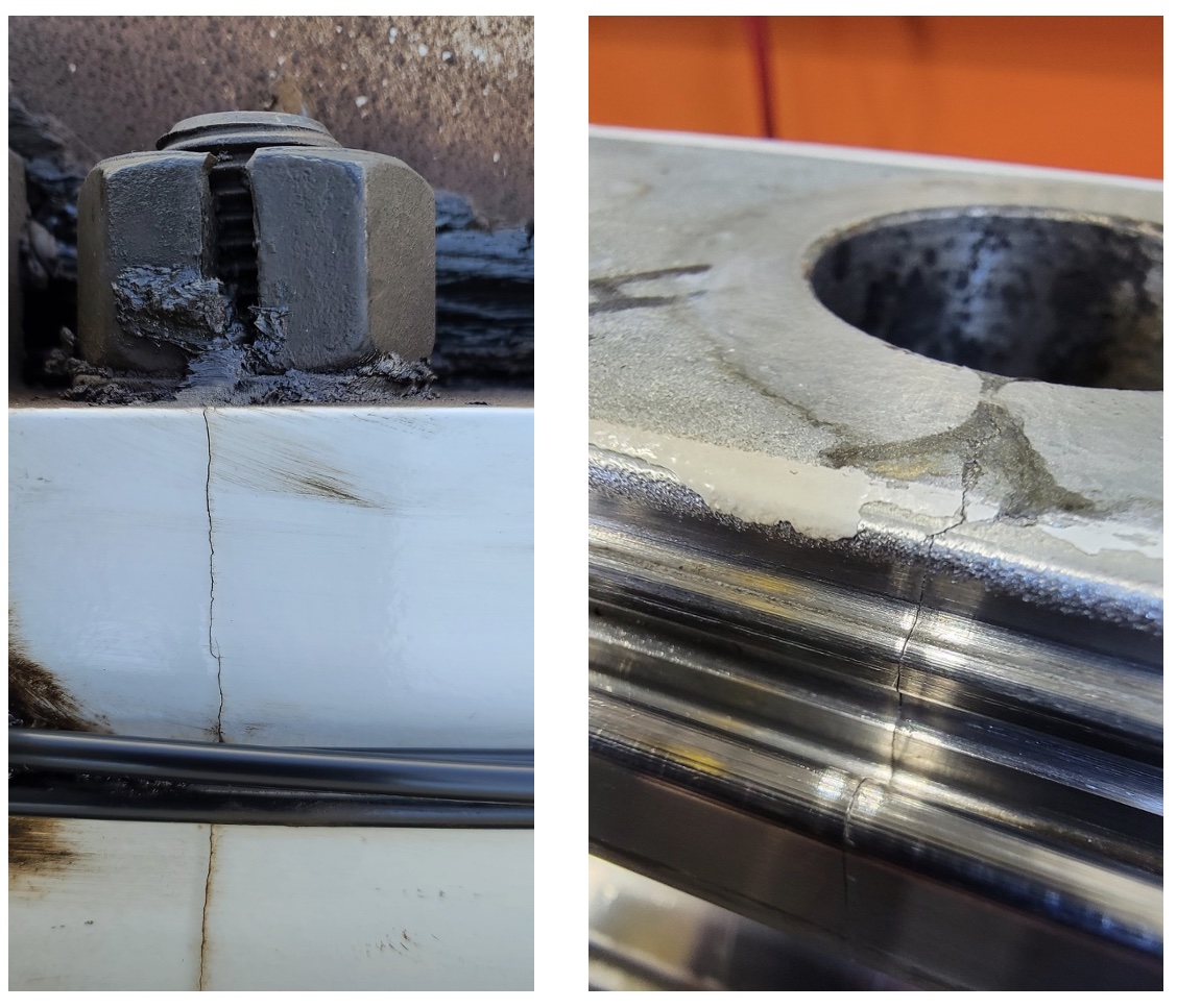
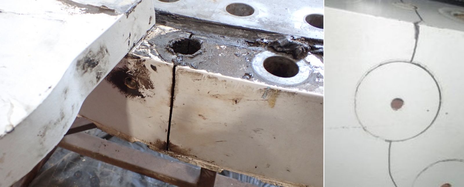
Once the crack starts in a blade bearing, there is no stopping it. The crack will continue to propagate from initiation point outward, and is known to lead to failing hardware (figure 5 below left), and even cracks in the hub. Additionally, one of the cracked bearings torn down and inspected had a second crack that was already approximately ¼ of the way through the cross-section, on the opposite side of the primary crack (figure 6 below right).
It is critical to the safety of personnel working in and near the turbine that cracked blade bearings be identified early, and shutdown, before additional damage to equipment puts their safety at risk. It is hard to predict the rate at which a crack will grow – if a crack is found, the turbine should be removed from service immediately. The eventual failure mode of a cracked bearing is the blade falling from the turbine.
Where to look for cracks
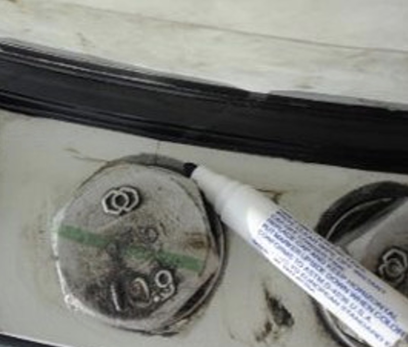 Because the cracks initiate in the outer ring bolt hole, just behind the blade side raceway, and grow in a circular pattern (Seen previously in figure 4), the first external area where a crack should become visible will be next to the seal, just inside of the mounting hardware (figure 7 at right).
Around the circumference of the bearing, there are multiple areas where cracks tend to form. The most obvious place to look is near sudden changes in system stiffness, such as lifting plates or stiffening plates (figure 8 below left). These plates create a stiffness joint, leading to additional concentration of stress; the bolt hole just outboard of the plate is often a cracking point. We have also seen cracks form near hub entry ports, and other areas without obvious attachments to the bearing that change the structural stiffness of the hub. Cracks through the filling plugs (figure 9 below right) are also known to happen. These manifest slightly differently than the cracks found through bolt holes, but ultimately have the same consequences, and need to be addressed immediately when found.
Cory Mittleider is a Mechanical Engineer with 13 years of experience in bearing applications, working on several wind projects including IOR Planet Bearings, other Gearbox Bearings, Main Bearings, and Blade Bearing inspections and evaluations. He helps provide solutions and long term reliability with upgraded replacement bearings.
Malloy Wind | malloywind.com
Author: Cory Mittleider
Volume: 2022 July/August