


Blade Bearing Cage Failure


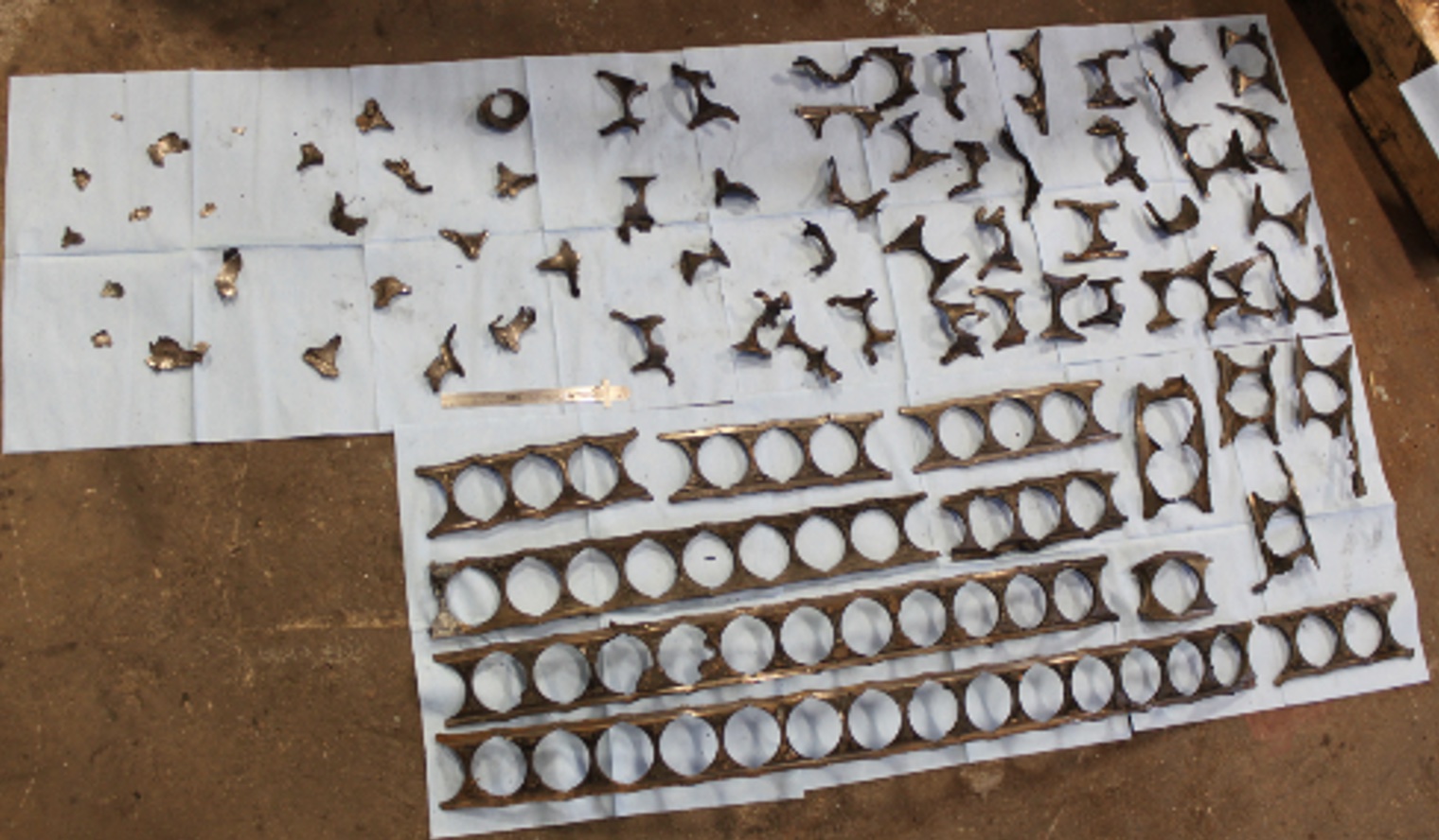
Figure 1: Blade bearing cage after 5 years in operation
Blade or pitch bearings connect a wind turbine’s blade to the turbine hub. These critical components are designed to hold the large aerodynamic, gravity, and rotational forces from the turbine’s blades. Most onshore wind turbines use a 2-row 4-point (2R4P) bearing design. These bearings generally consist of a cage to separate the balls, bearing seals on the hub and blade sides to prevent contamination, and inner and outer rings with integrated bolt holes. (Figure 1) Also note the filling slots/plugs on the outer ring: these are necessary for 2R4P bearing assembly. 2R4P bearings have 2 rows of balls, each with 4 points of contact with the bearing raceways (hence their name). While these bearings are generally designed to operate for around 20 years, many do not last that long. There are a variety of failure modes that can result in premature blade bearing failure, but one common premature failure mode is bearing cage failure.
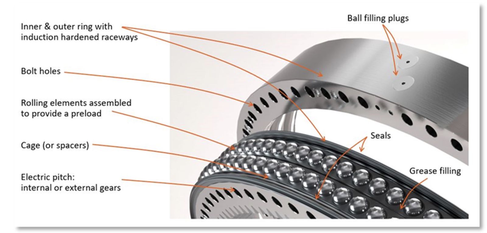
Figure 2: Blade bearing anatomy
What is a bearing cage?
A bearing cage is a component used in bearings to separate and maintain the proper position of the rolling elements within the bearing. The cage serves to keep the rolling elements evenly spaced, and helps to reduce friction and wear. Cages are typically made from materials such as metal or plastic. Today’s 2R4P blade bearings utilize steel cages, but some of the first blade bearings used plastic spacers.
As turbines grew larger, spacers started to get crushed by the bearing rolling elements to the point where balls began to bunch together and roll against one another. To combat this, manufactures began using steel cages that are stronger and more resistant to wear. However, in some platforms, even these steel cages have begun to deteriorate or break up over time. In general, bearing separators are not meant to carry load — their main purpose is to separate the rolling elements. Cage loading will always shorten bearing life. So why are these failures occurring? Plastic spacers work just fine in other applications using 2R4P bearings. They are even used in most wind turbine yaw bearings that have the same raceway design! How could steel cages be failing?
To understand the root cause of this issue, one must first understand how 2R4P bearing’s carry load. A 2R4P bearing’s balls are preloaded and designed to carry load at their 45-degree contact angle (Figure 3A). This 45-degree contact creates forces that can be resolved into both axial and radial components. (Figure 3A) The radial component of the forces pushes the bearing outer ring out, while pushing the inner ring in. This leads to increased bearing ring separation and hub deformation, which allows the contact angle of the ball to change. (Figure 3B) This change in contact angle allows the ball’s hertzian ellipse to approach the raceway edge, decreasing the contact area of the ball with the raceway, which then increases the stress on the raceway edge. (Figure 3C) This phenomenon is also commonly referred to as ellipse truncation. While this concept is key to understanding cage failure, it can also lead to raceway edge wear and fracture.
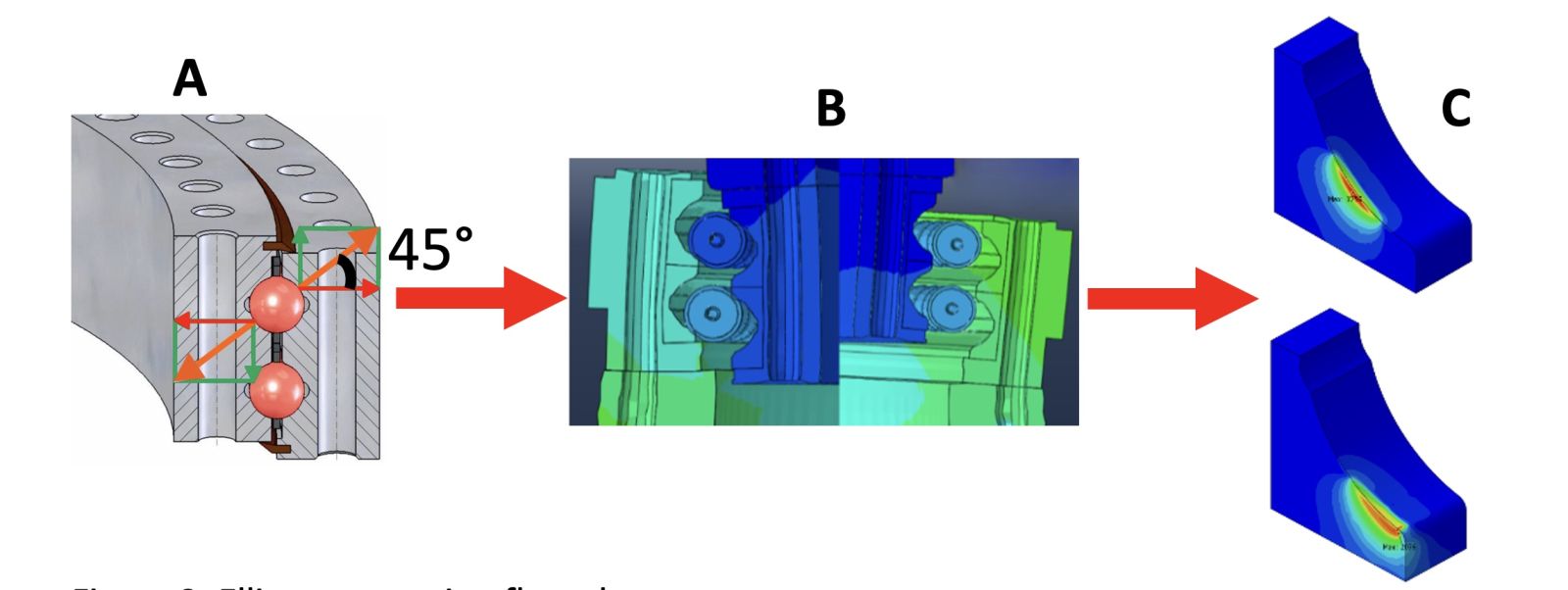
Figure 3: Ellipse truncation flow chart
How does a change in contact angle effect the bearing cages?
When all balls in the bearing have the same contact angle, they roll at the same speeds. When a large moment load is applied to a pitch bearing, different areas of the bearing are subjected to different magnitudes of force. For instance, the large aerodynamic forces on the blade create a bending moment that pulls the upwind side of the bearing away from the hub, while the downwind side is being pushed into the hub. Yet, near the bending plane, the bearing is subjected to less direct loading from the bending moment. That is why the filling plugs or slots in 2R4P bearing’s outer rings are installed so they are near said bending plane. They represent a weak point in the bearing design, so they are positioned in the least loaded area of the bearing. This variable loading along the bearing perimeter, in combination with the complex geometry of the hub, allows for varying degrees of deformation and, therefore, ellipse truncation around the bearing perimeter. When balls in the same bearing have different contact angles, they will attempt to roll at different speeds, creating cage loading. (Figure 4)
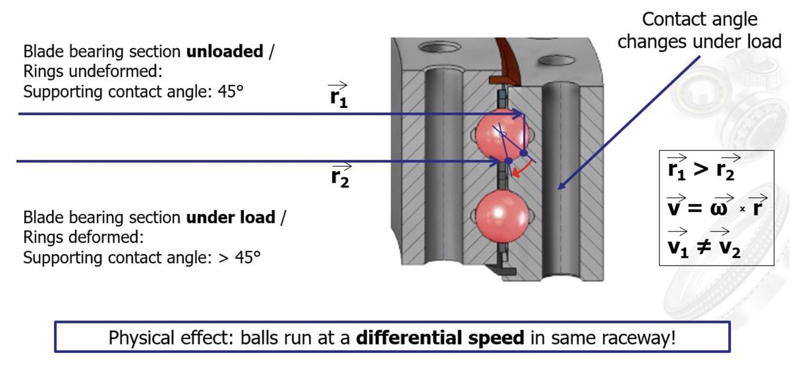
Figure 4: Contact angle, and cage loading
What does cage failure look like?
In the initial stages of cage failure, there will be little signs that indicate there is a problem. Grease sampling is one of the best ways to identify that there may be problem during early stages. As damage progresses, the iron content in the bearing’s grease will continue to increase. Eventually the cage will wear enough to begin breaking apart. (Figure 1) Cage pieces can then push out the bearing’s seals, allowing lubricant to leave the bearing, and in many cases, run down the blade itself. (Figure 5) Pieces will also fall from the bearing onto the ground, causing safety concerns as many of these cage pieces can we quite sharp. Cage pieces will also start to block the rolling elements, much like a rock under the wheel of a shopping cart. This increases the torque necessary to rotate the bearing. The increased torque causes the entire pitch system to work harder, potentially causing failures outside of the pitch bearing as well. Given enough debris, the bearing will lock up, resulting in premature pitch bearing failure.
Figure 5: Cage sections pushing out bearing seals
Nathan Stan is a Mechanical Engineer (MS) with Malloy Wind, a wind service and parts supplier who is celebrating 25 years supporting wind turbine operators. Nathan is their blade bearing focused engineer. He has performed failure investigations on a wide variety of blade bearings across multiple OEMs to help operators better understand failures occurring in the field, and help provide solutions with long term reliability in mind.
Malloy Wind | malloywind.com
Author: Nathan Stang
Volume: 2023 March/April