

Solar Safety Standards Pave the Way to a Low-Carbon Future


Businesses are steadily striving to become self-sufficient power producers that can generate, store, consume and even sell excess renewable energy back to their utility. However, these capabilities hinge on two layers of connectivity - connection to the local power system and interconnection with the larger utility grid. It is critical these connections are made with the overall safety and reliability of the system in mind.
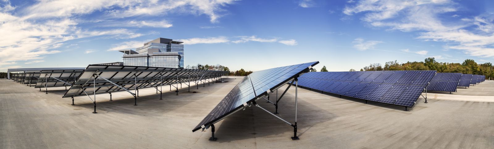
© David Sundberg/Esto
Codes and standards for safe PV system installation
There are a number of National Electrical Code (NEC) guidelines for the safe installation of solar PV systems. It is always important to keep NEC Chapters 1-4 in mind. These foundational guidelines provide many important safety requirements for wiring, conductor protection and sizing, temperature considerations, and more. The other primary NEC Articles you should familiarize yourself with include:
- NEC Article 690
Article 690, consisting of eight parts, applies to PV electrical systems, array circuits, and inverters for PV systems, which may be interactive with other electrical power sources (the electric utility) or stand-alone (with or without energy storage). - NEC Article 691
Article 691 covers the installation of large-scale PV electric supply stations with an inverter generating capacity greater than 5000 kilowatts (kW) that are not under exclusive utility control. - NEC Article 705
NEC Article 705 addresses how to connect additional power production sources to the existing wiring system to operate in parallel with the primary source of electricity. Typically, the primary source is the electric utility; other local sources could include onsite energy storage, solar, wind, fuel cells, or generators.
While these NEC Articles are a fantastic starting point for understanding safe solar PV system installation, they are not intended to serve as a design guide. For one, the NEC is written to provide minimum requirements for fire and personnel safety. Additionally, every solar PV installation is different; this means you can often design a PV system that meets all minimum code requirements but isn't optimized for the environment, which creates uptime and production challenges. From this perspective, it is vital to consider going above code requirements to ensure overall effectiveness and safety.
4 tips for designing safer, more productive solar PV systems
- Plan for peak conditions
Overcurrent protection devices (OCPDs) provide vital functionality enabling cost-effective and reliable performance of PV systems. However, peak solar project site operating conditions are often not considered when sizing AC collection system components. This can lead to equipment overheating, nuisance tripping, system failure and reduced power generation during hot summer days when reliable power production is needed the most.
Peak site conditions act individually or in concert to increase the internal operating temperatures in equipment enclosures, and can stress components well beyond design ratings. Common peak conditions include ambient operating temperatures approaching or exceeding 40 °C, internal heat gain due to direct solar radiance on the enclosure or reflected from the terrain, and geographical elevations above 3,300 feet.
PV system designers often use 2 percent high or 0.4 percent high weather temperature data as the basis for system design, then size the PV system ampacities to minimum NEC requirements without taking additional thermal rating factors into consideration.
This presents problems during the hottest summer days, when peak daily temperatures reach record levels. The IEEE C37.24 "Guide for Evaluating Effect of Solar Radiation on Metal-Enclosed Switchgear" is an excellent reference on this topic. For enclosures subjected to full sun exposure, the reflected solar gain and the direct solar gain can add up to 15 °C to internal enclosure temperatures. This means the internal enclosure operating temperatures can exceed 50 °C for an extended period (4 to 6 hours) during the peak of the solar day, even in moderate climates. Effective thermal management is required to address this challenge.
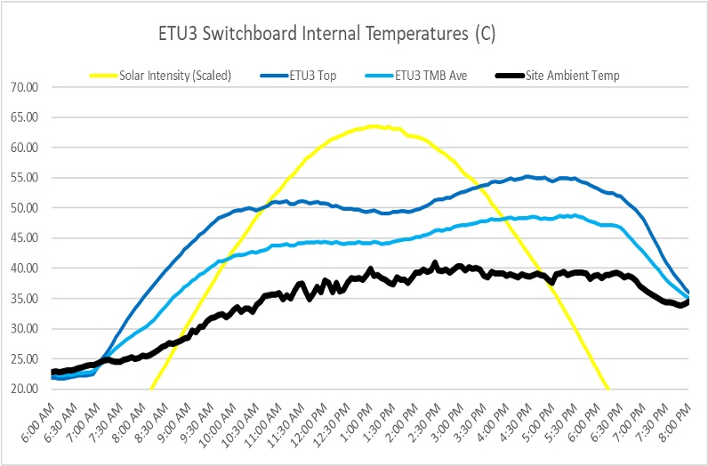
Chart displaying internal switchboard enclosure temperatures on a day with local area high of 37 °C, demonstrating solar reflective heat gains of approximately 2-4 °C and an internal enclosure temperature increase up to 15 °C.
- Properly select OCPDs
As discussed above, peak site conditions like solar radiance can often exceed UL equipment design ratings. For example, UL891 Switchboards, which utilize molded case circuit breakers and fused switches as OCPDs in enclosures, are UL Listed based on 40 °C ambient with 65 °C rise at maximum loading. For environments with internal enclosure temperatures above 40 °C, you can apply the following thermal management strategies to help prevent equipment overheating and OCPD nuisance operation:
- Reference thermal rating factors published by manufacturers for OCPDs in service temperatures above 40 °C
- Sizing OCPDs for 50 °C ambient service should be considered a best practice for solar PV applications
- Recognize that OCPDs acting as string inverter AC collection devices will often be densely packed and highly loaded at the same time during the peak temperatures of the solar day, which impacts ambient service temperatures
- Size switchboard buses properly for system loading. Consider upsizing to the next ampacity to reduce heat rise based on thermal conditions
- Ensure equipment and OCPD terminal connections are UL rated for conductors applied at 75 °C, even if 90 °C rated conductors are applied.
- Size conductors for thermal conditions
Conductors are an important thermal management system that draw heat out of the OCPD during operation. Applying the conductors at 75 °C ratings to match the OCPD terminal UL Listing is recommended. The conductors should also be sized per NEC 310 with applicable NEC conductor thermal rating factors applied. For example, the NEC 2020 Table 310.16 provides the allowable 75 °C ampacities of insulated conductors based on 30 °C ambient temperatures, and Table 310.15(B)(1) provides thermal correction factors for ambient temperatures above 30 °C. Sizing cables for 50 °C service in solar applications is a good way to reduce the temperature rise in the enclosure.

Thermal field scan showing molded case circuit breaker overheating due to undersized cables exceeding 75 °C UL terminal ratings.
- Go beyond the code to enhance safety
The NEC provides an exception [2020 NEC 690.9(D)] that eliminates the requirement for a main overcurrent protective device on the inverter side of the solar power transformer. This exception states that a power transformer with a current rating connected toward the interactive inverter output, not less than the rated continuous output of the inverter, shall be permitted without overcurrent protection from the inverter.
Although the elimination of the main OCPD on the secondary of the solar power transformer may provide economic benefits to the project cost, this approach increases arc energy hazards for operation and maintenance teams precisely where available arc fault energy is at its highest level.
System designers may want to consider employing arc flash reduction measures at the low voltage side of the solar step-up transformer. To achieve this, incorporate an Arc Reduction VFI (AR-VFI) transformer design or add the main OCPD back into the design with an approved NEC 240.67 Fuse or NEC 240.87 Circuit Breaker to provide an arc energy reduction method for circuits 1200 amps and above.
Technologies that convert energy from the sun into electrical power have matured. They are more cost-competitive, driving significant increases in renewable power generation around the world. Yet, adding solar installations to building electrical systems is complex -it's important to understand that NEC installation requirements serve as a bare minimum. Going above and beyond code requirements when designing PV systems will help supply reliable and safe power for years to come.
Lawrence T. Conner is an Energy Transition Senior Application Specialist, and
Jaska Tarkka is an Energy Transition Application Engineer at Eaton, a single-source supplier of electrical balance of system solutions for residential, commercial, and utility solar power installations.
Eaton | www.eaton.com/solar
Author: Lawrence T. Conner and Jaska Tarkka
Volume: 2021 September/October

.png?r=5072)