

Solar Racking in Extreme Weather Conditions


Just like any other structure, racking systems for solar modules need to withstand wind, snow and seismic actions imposed by nature. Research over the past 10 years along with the state-of-the-art building codes and wind loading standards ASCE 7-16 and SEAOC PV-2 2017 define the requirements that need to be met. Those prescribe how to test for solar structures, analyze wind tunnel data, and reduce it to an amount that the racking manufacturer can handle.
The desire to install solar modules on a variety of sloped or flat rooftops at different building sizes and heights, as well as for ground mounted systems on level or uneven terrain, require some solar racking systems to be fully or partially attached, while others might resist those forces by ballast only.
.jpg)
Usually, building codes worldwide demand a solar system to be designed for a return period or recurrence interval - the estimated average time between extreme events such as windstorms, snowstorms or earthquakes, etc. Fortunately, the peak maximum wind loading does not co-occur with the peak maximum snow loading. The reason is that severe windstorms do not come with much snow. In contrast, heavy snowfall does not come with extreme wind speeds. The continuously updated codes and standards which are based on science and experience recognize the lack of simultaneity and account for it by load combinations.
These considerations relate to wind, snow and seismic actions. However, one also needs to look at the resistance of the individual components and at the overall stiffness of a racking system. With regard to the latter, testing for load-sharing, e.g. the system's ability to share loads acting on one solar panel with adjacent solar panels which depends on the structural interconnection of modules via brackets, rails and clamps, has established itself as an industrial practice for ballasted racking solutions. In addition, the mechanical load test of UL 2703 provides the maximum loading that a solar racking system can withstand.
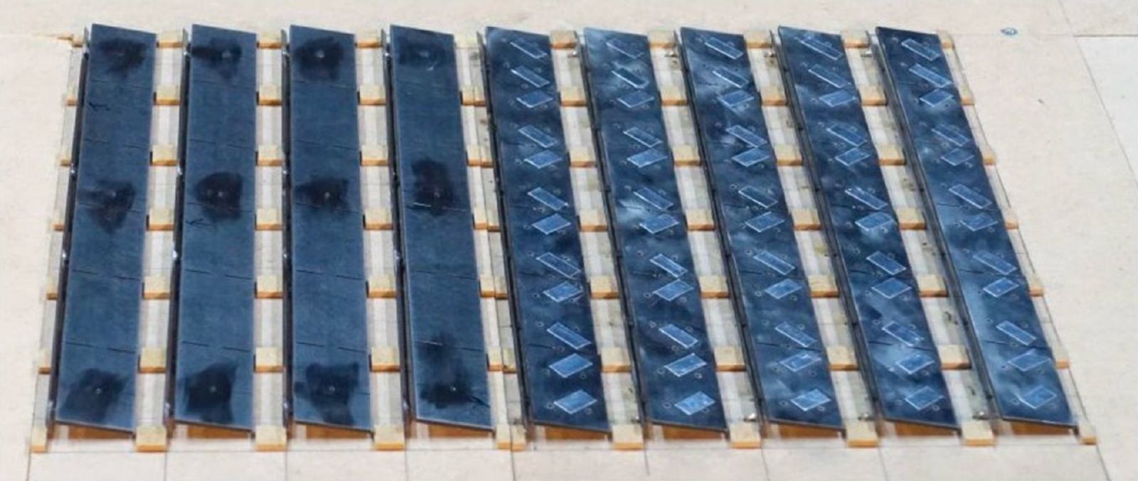
Figure 1: Wind tunnel model of a roof-mounted solar array
Having reviewed many projects, it is my experience that at many sites the wind can approach the target building from a 30 °-wind sector without any obstacles or with few obstacles in its way. If such condition is given, it is more prudent to design for Exposure Category C while there may be some room for interpretation if in the strict sense such selection would be enforced by the building code. While in the ongoing pandemic staying safe is a must, designing safe is an eternal must.
The design of roof-mounted solar arrays is affected by a range of building- and system-related parameters including, but not limited to building plan dimensions, building height, parapet height, roof zones, array geometry, array zones, gaps or rooftop obstructions, row spacing, uplift and sliding load cases, tributary area, array setback distance from roof edges, roof slope, and open or enclosed buildings. In addition, ballast layouts need to be tailored to any array shape for roofs of any shape including flat roofs, roofs of high-rise buildings and odd roof shapes such as L-, T- or U-shapes, stepped roofs or any combination of these. Lastly, higher adjacent buildings may significantly affect the wind loading on solar arrays placed on a nearby building, the effects of which need to be evaluated on a case-by-case basis with little to no general design approach.
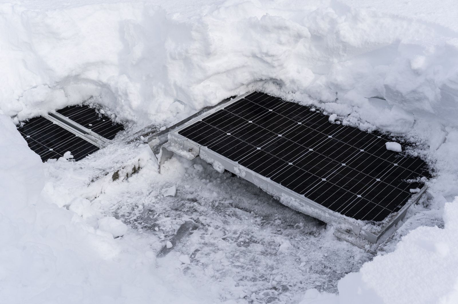
Figure 2: Roof-mounted solar racking system buried under snow layer
Accounting for the above-given parameters in solar array design requires world-class engineering based on wind tunnel reports of which not all of them are made equal. Wind tunnel testing related to solar structures needs to be conducted in boundary layer type wind tunnels with the spatial-temporal correlation of fluctuating pressures measured using high-frequency sampling. Moreover, the analysis of aerodynamic coefficients requires appropriate state-of-the-art methods which need to account for model scales used in the testing not matching the scale of flow simulation. Since the correctness of all the above usually cannot be evaluated by non-wind engineers, peer-reviewed wind engineering reports for roof-mounted solar structures are enforced by ASCE 7-16 and SEAOC PV-2 2017.
Drifting and sliding snow which build up on the modules and racking pose additional challenges for solar arrays and for the roof structure underneath, require associated structural engineering and enhance the need for appropriate testing. Real-world exposure in extreme climates such as in the Austrian Alps helps verifying engineering assumptions.
In brief, the interaction of the various loads on solar modules and racking systems is complex due to the large number of parameters to be considered. However, it is possible to design solar systems safely and economically by strong internal engineering capabilities and reliable partners for wind tunnel testing, structural engineering, and powerful design software.
AEROCOMPACT was founded in Austria in 2014. It designs, engineers and manufactures flat roof, ground mount, and metal roof solar mounting solutions. The company has locations in Austria, the USA and India and an additional 14 sales offices around the world, and has installed around 1 GW of power
AEROCOMPACT, Inc. | www.aerocompact.com
Author: Dr.-Ing. Thorsten Kray