

Solar for Florida’s Hurricane Zone


The challenges of designing the uplift stability of solar panels in the Florida counties of Miami-Dade and Broward are immense, and with good reason. Hurricane Andrew made landfall in South Florida in 1992, with wind speeds recorded up to 177 mph. The $25 Billion worth of damage was primarily caused by these high winds (as opposed to storm surge, which typically causes the most damage). Accordingly, the 2020 Florida Building Code specifies the design wind speeds of 175 mph for Miami-Dade, and 170 mph for Broward (FBC 1620.2). Respectively, this is a 64 percent and 59 percent increase in wind speed — far above the 107-mph limit used in Miami, Indiana. However, since wind pressure is the square of windspeed, the increase in wind pressure actually ends up at 167 percent for Miami-Dade, and 152 percent for Broward County.
In addition, the Florida Building Code requires that a minimum of Exposure C is used in high velocity hurricane zones (FBC 1620.3). Exposure is the consideration of what other types of structures are near the structure in question. A house in a neighborhood with other similar houses around it will be Exposure B; a farmhouse with fields surrounding it will be Exposure C. This means another increase of about 40 percent for a 30-foot-tall structure, which would normally be considered Exposure B.
For those keeping score (and with all things being equal) designing solar attachments in Miami, FL is 3.24 times that required for Miami, IN.
Let’s look at an example of a typical residential layout. A gable roof with a 5:12 (23 degrees) pitch could yield the following design uplift on the solar panels:
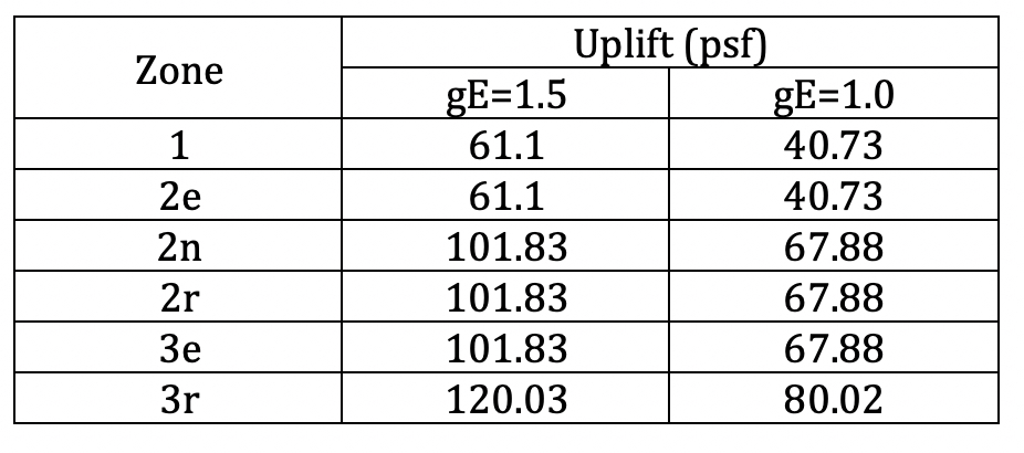
In the chart above, the gE is the array edge factor. Generally, when any edge of the array is greater than half the building height away from the roof edge, gE=1.5. In other words, we need to add another 50 percent uplift for those panels.
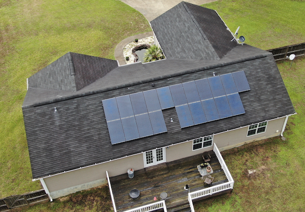
This image shows a condition where a plumbing vent has interrupted the array layout. This results in the adjacent North panel having an exposed edge and, consequently, a significant increase in design uplift.
The uplift effects on the rail and attachment anchors is manageable. Reducing the spacing of the anchors will shorten the span of the rail, thus lowering the bending stress. This also distributes the load to more anchors so each anchor has a lower pullout force. To get more capacity out of each anchor, another option is to increase the depth of the lag bolt into the rafter below, which will increase the withdrawal capacity of the anchor.
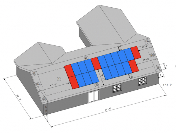
This model shows the dimensions of the panels from the edges of the roof. Note that the building height h=13’ so any panel within half that distance (7’-6”) from the roof edge must have the gE factor of 1.5 applied.
One component we have no control over is the uplift capacity of the solar panel itself. Although uplift ratings on panels differ, a typical rated wind uplift value is 4,000 Pa (83.5 psf). A 1.5 safety factor is required to be applied to the rated value, which brings the allowable uplift to 2667 Pa (55.7 psf). For most of the United States, and most array configurations, this allowable capacity far exceeds the design uplift applied to it. It should be noted that these ratings are assumed to be for portrait orientation only, and do not apply to the long side of the panel placed parallel with the rails (landscape).
Back in Miami, FL — given the example above — as long as we stay in zones 1 or 2e AND we make sure that all edges of the array are not “exposed”, these panels will be sufficient. In a perfect world, we can ensure this every time. However, in reality, more often than not, we cannot feasibly keep all the panels within these conditions without diminishing system sizes or making significant changes to the building components itself.
Additional testing is occasionally performed by the panel manufacturers to achieve a higher uplift rating typically coming in around 5,600 Pa (117.0 psf), which, with a safety factor, comes to 3733 Pa (78.0 psf). This significantly improves our options of where panels can be installed to zones 1 through 3e for not “exposed”, and zones 1 and 2e where panels are considered exposed.
Our recommendation to our clients is to always design your PV system with panels that have already been rated at a higher level, allowing for more flexibility in array layout. Check with your engineer for a database of solar panels that meet the strict requirements of Southern Florida.
Andrew Leone is the Owner of Penn Fusion Engineering, which provides the solar industry with structural analysis of rooftops of all types (residential and commercial).
Penn Fusion Engineering | www.pennfusioneng.com
Author: Andrew Leone
Volume: 2023 May/June