

Pressures to Point Loads: How Solar Impacts Rooftop Wind Dynamics


Building codes and minimum building standards such as ASCE 7, Eurocode, and the National Building Code of Canada, are used to calculate the maximum forces a building may encounter. These forces result from wind, snow and seismic activity. For wind uplift, the roof assembly is designed to resist the maximum calculated uplift pressures, which vary depending on geographic location — from relatively moderate winds to extreme hurricane velocities in mountainous and coastal areas.
How solar alters wind uplift
Installing rooftop solar alters the wind dynamics influencing how uplift pressures impact a roof. When solar modules are added, they take the brunt of uplift pressures instead of the roof. The modules transfer concentrated loads to the roof at each attachment point. While roofs are designed to withstand distributed uplift pressures, they cannot always resist the point loads from the solar attachments. Therefore, it is necessary to evaluate and validate the roof’s capacity to withstand these load conditions. A well-designed mounting system can protect the solar modules and the roof from these uplift pressures (or even stronger ones), protecting both the solar array and the structural integrity of the roof.
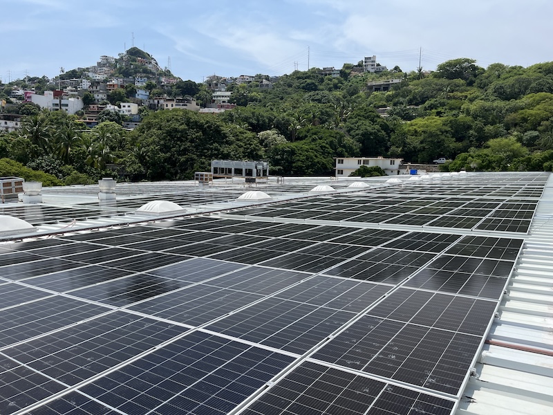
Roof mounted system remains intact after Category 5 hurricane winds strike Acapulco, Mexico in 2023
Understanding wind uplift on roofs
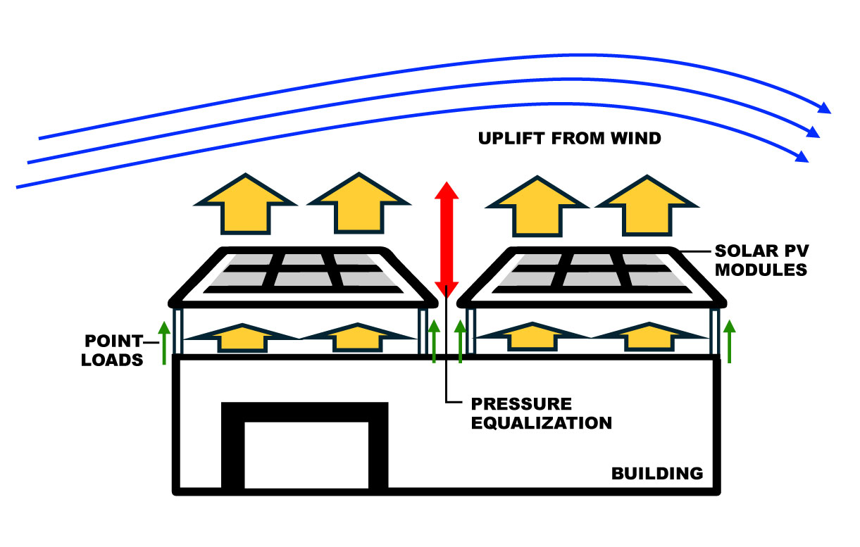
Uplift forces on a roof’s surface are generated by wind re-direction over a building, increasing velocity. This creates suction above the roof. Internal pressure from an open door or window adds positive pressure inside a building, augmenting the uplift pressure. The image below illustrates these dynamics.

The dynamics work as expected across the top of a roof — greater wind speed equals greater uplift force. Other factors can increase the uplift pressure, such as the height and breadth of walls, surrounding topography, and proximity to open water. Special use buildings, like schools and hospitals, also require higher safety factors in design. Under-designed roofs are prone to damage or failure.
Roof system design
Once the required design pressure is calculated, the roof system is constructed to achieve (or exceed) that pressure. Roofing manufacturers provide different system combinations of roofing material, fasteners, clips, adhesives, etc. The details vary with the desired strength rating. For instance, the spacing between fasteners attaching the membrane to structure can be closer to achieve higher uplift resistance.
Roofing systems are tested and certified to achieve specific ratings. FM 4471 (metal roofing) and FM 4470 (single-ply membranes) are examples of the many standards used. For instance, a metal roofing system listed to FM 4471 can resist uplift pressures of 105 psf. To achieve such ratings, each component in the system must be installed according to specification.

Wind dynamics with rooftop solar
As winds flow over a roof with solar panels, the array bears most of the uplift force. If the array is ventilated (gaps between the modules), uplift pressure is reduced across the modules, transferring some suction back to the roof. This splits the pressure between the two surfaces. According to ASCE 7 standards, design pressure on solar modules is lowered up to 40 percent depending on the array configuration. This pressure is now shared between the panels and the roof, and must be accounted for in both parts of the system.
To ensure the solar installation can resist the design wind uplift pressures, the PV modules, mounting systems, and roof attachments must be evaluated using relevant certifications and test data. Listings like UL 61730 and UL 2703 are generally adequate to demonstrate that the uplift resistance meets design requirements. External seam clamps, which are components installed directly onto metal roof seams, have also been documented (ASTM E1592, FMDS 1-31) to improve the uplift resistance of metal roofing.
Following the load path
The uplift dynamic for the roof system is different. While the roof may experience only a fraction of the total uplift pressure, it will still be subjected to point loads at the attachment points where the roof and the solar installation connect. This difference can be understood by following the load path. The uplift pressure on the solar modules generates point loads that are transferred to the roof via either rail or rail-less roof attachments.
From the array, the forces follow the load path, from the roof sheet (when applicable) to any clips, fasteners or adhesives attaching it, and finally into the sub-structure and rafters. Each connection point in this load path must be evaluated to ensure its strength. This can be achieved by using certification data, such as a Factory Mutual (FM) approvals listing or other assembly testing, to validate the implied allowable strength of each component and connection along the load path. While some projects may request system testing all along the load path, this is often unnecessary when validated data or listings for the connection points accurately represent real-world use.
Hurricane Otis case study
The photograph below illustrates the concepts described above. A large retail store with a solar array installed on its metal roof utilized a direct-attach solar mounting system with standing seam roof clamps. In 2023, during Category 5 Hurricane Otis in Acapulco, Mexico, sections of the roof protected by the solar installation fared much better than the roof without it.
The solar modules absorbed much of the uplift pressures, while the roof’s metal panels were also enforced by seam clamps used in the mounting system. Uplift loads were split between the solar modules and the metal roof, reducing the pressure on each. Although the hurricane forces exceeded the roof design, the solar attachments to the roof, clips, fasteners and purlins remained intact, validating that the point loads did not exceed the capacity of the connections between components. Direct-attach systems generally have more roof attachment points, distributing lower point loads to better resist hurricane-force wind forces. Additionally, the standing seam clamps used to attach the solar modules to the roof functioned as external seam clamps previously discussed, further increasing the strength of the roof sections directly underneath the solar installation.
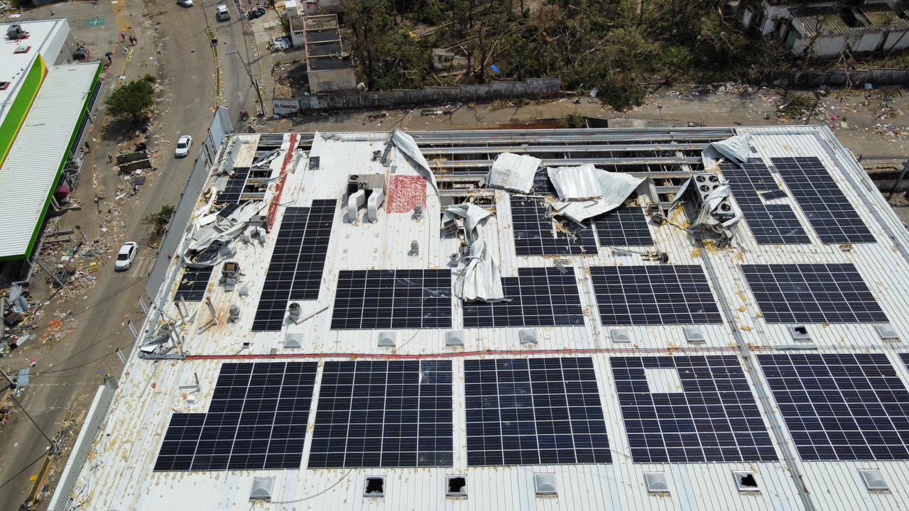
Aftermath of Hurricane Otis; Acapulco, Mexico; 2023
Main take-away
Installing rooftop solar fundamentally changes the wind dynamics acting on a building’s roof from uplift pressures to a system of point loads. It is crucial to follow the load path, converting pressures into point loads at each connection. The system should be thoroughly analyzed using a combination of component testing, certifications, and allowable strength ratings. This ensures that the design is capable of withstanding high winds while keeping the solar and roof intact.
Mark Gies is Director of Strategy and Market Development at S-5! With 16 years of solar energy industry, Mark has experience ranging from product development, operations, installation, compliance, codes and standards, to sales and business development. He is the vice-chair of SEIA’s Mounting System Manufacturers Committee, a member of SEAOC’s PV Committee, and a founding member of UL 2703’s Standard Technical Panel.
S-5! | www.s-5.com
Author: Mark Gies
Volume: 2025 July/August