


NEC2026: What’s New for Solar Labeling Requirements?


Code-Making Panel 4 of the National Electrical Code recently completed its final changes to the NEC2026 code for articles related to labeling within the solar industry including PV labeling requirements.
After reviewing public input late in 2023, the first draft of the new code was completed in January 2024. Soon after, the public had the opportunity to review these changes and offer further commentary. The panel discussed and finalized the feedback before passing the final vote last October.
Most changes were editorial in nature – either correcting errors, simplifying requirements or moving items to more appropriate locations.
Unless the NEC Correlating Committee makes any alterations to the panel’s recommendations, the new code will be published in 2025. As of today, the changes outlined in this article are accurate to any revisions, additions, deletions or changes to labeling requirements.
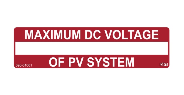
The label required for 690.7(D) has been updated to allow the PV dc circuit maximum voltage to be rounded up the greater value than that calculated in 690.7. So, instead of five labels with very specific voltages, the installer can use one label with a rounded voltage to allow standardized labeling. This was also done to harmonize with the new definition of PV system circuit nominal voltage. The exception is that if the marked dc voltage on the equipment is equal to the nominal system dc voltage, additional marking is not needed.
Article 690.9(D) now indicates that OCPDs (Overcurrent Protection Devices) used in PV system dc circuits shall be marked Photovoltaic or PV. The new subdivision (D) was added to clarify that OCPDs used in these circuits must be marked as stated to meet the requirements in this article. Changes were made to align references related to overcurrent protective devices with their defined terms and acronyms.
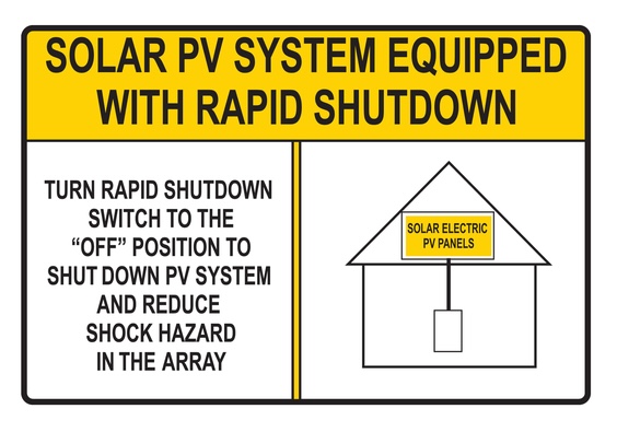
An editorial change was made to 690.12(D) because the language was not consistent with the label. The new language is as follows:
SOLAR PV SYSTEM IS EQUIPPED WITH RAPID SHUTDOWN.
TURN RAPID SHUTDOWN SWITCH TO THE “OFF” POSITION TO SHUT DOWN
PV SYSTEM AND REDUCE SHOCK HAZARD IN ARRAY.

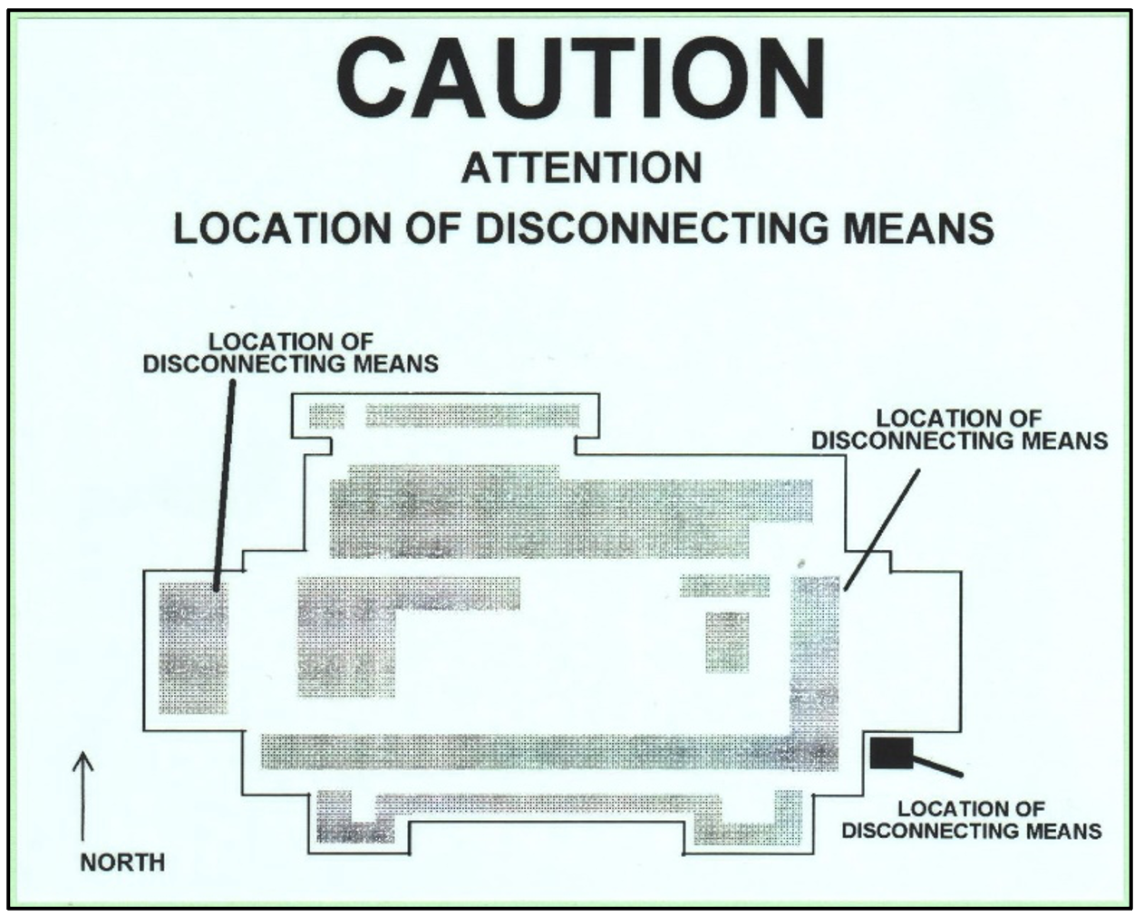
The label requirement as currently listed in 690.13(B) has been simplified to only indicate that: Each PV system disconnecting means shall be permanently marked “PV SYSTEM DISCONNECT” or equivalent.
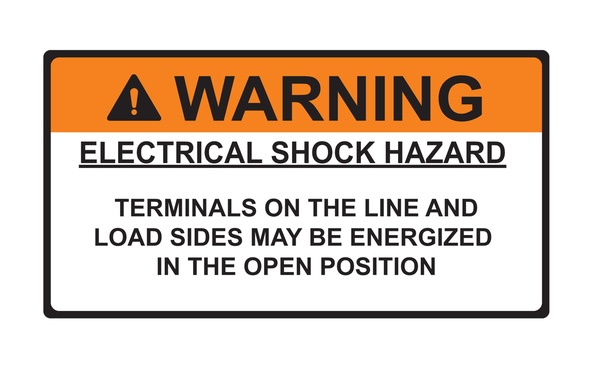
The Electrical Shock Hazard label shown above has been eliminated from 690.13(B). Since the code is now pointing to all PV system disconnects having to comply with 705.20(F), the line and load terminal warning label will be located there, rather than repeat it in two places. A similar example can be found in article 690.15(C)(4), which now states that: Equipment disconnecting means, other than those complying with 690.33, shall be marked in accordance with the warning in 705.20(F), if the line and load terminals can be energized in the open position.
For editorial reasons, 705.20(7) has been renumbered as 705.20(F) and text added to clarify that the terminals are for the disconnecting means. See change below.
“Where the line and load terminals of the disconnecting means are capable of being energized in the open position, be marked with the following words or equivalent:”
WARNING
ELECTRIC SHOCK HAZARD
TERMINALS ON THE LINE AND LOAD SIDES
MAY BE ENERGIZED IN THE OPEN POSITION.
The title of 692.17 was changed from “Switch or Circuit Breaker” to “Equipment Disconnecting Means” and moved to Article 692.15.
Similar editorial and location changes were made for Article 690.31 in which (B)(1) to B(3) were deleted and moved to 705.25(B)(1) to (B)(3), since the marking requirements apply to all PV dc circuit conductors and not just those on the PV power source output. Some of the following text is struck out because the specific requirements for marking are already covered in article 210.5(C)(2).
690.31 (B)(1) to (B)(3) Identification is now moved to 705.25(B)(1) to B(3)
PV system dc circuit conductors shall be identified at all termination, connection, and splice points by color coding, marking tape, tagging, or other approved means in accordance with 690.31(B)(1) to 690.31(B3) 705.25(B)(1) through 705.25(B)(3).
Conductors that rely on other than color coding for polarity identification shall be identified by an approved permanent marking means such as labeling, sleeving, or shrink-tubing that is suitable for the conductor size.
The permanent marking means for nonsolidly grounded conductors shall include imprinted plus signs (+) or the word POSITIVE or POS durably marked on insulation of a color other than green, white or gray. The permanent marking means for nonsolidly grounded negative conductors shall include a negative sign (-) or the word NEGATIVE or NEG durably marked on insulation of a color other than green, white, gray or red. Only solidly grounded PV system dc circuit conductors shall be marked in accordance with 200.6.
Where requirements apply more generally, terms in the sections moved to 705.25 have been adjusted to refer to conductors without the use of specific wire or cable types. The section that was edited and moved is shown below:
705.25(B) Identification of DC Power Source Output Conductors.
Color coding, marking tape, tagging, or other approved means in accordance with 705.25(B)(1) through 705.25(B)(3) shall be used to identify dc power source output conductors at all termination, connection, and splice points.
(1) Positive Polarity.
Identification of dc positive conductors shall occur by one of the following means:
(1) Imprinted plus signs (+) or the word POSITIVE or POS durably marked on conductor insulation.
(2) An approved permanent marking means (e.g., sleeving or shrink-tubing) that is suitable for the conductor size at all termination, connection, and splice points, with imprinted plus signs (+) or the word POSITIVE or POS.
(2) Negative Polarity.
Identification of dc negative conductors shall occur by one of the following means:
a. Imprinted minus signs (–) or the word NEGATIVE or NEG durably marked on conductor insulation.
b. An approved permanent marking means (e.g., sleeving or shrink-tubing) that is suitable for the conductor size at all termination, connection, and splice points, with imprinted minus signs (–) or the word NEGATIVE or NEG.
(3) Color Identification.
Where color is used, identification shall occur by one of the following means:
(1) For nonsolidly grounded dc positive conductors, marked with an insulation color other than green, white, or gray.
(2) For nonsolidly grounded dc negative conductors, marked with an insulation color other than green, white, gray, or red.
(3) For solidly grounded dc conductors, marked in accordance with 200.7.
Informational Note: See Article 100 for the definitions of functionally grounded and solidly grounded.
(C) Grounded Conductors of Different Nominal Voltage Systems.
If functionally or solidly grounded conductors of different nominal voltage systems are installed in the same raceway, cable, box, auxiliary gutter, or other type of enclosures, the following shall apply:
(1) Each grounded conductor shall be identified by nominal voltage system.
(2) Identification by color coding, marking tape, tagging, or other approved means shall be permitted.
(3) The means of identification shall be documented in a manner that is readily available or permanently posted where the conductors of different nominal voltage systems originate and terminate.
As you can now see, DC power requirements in 705 are now in a better place with similar marked wires. The proposal clarifies the polarity and color identification requirements that should be applied for DC and AC power source circuits. DC wiring from multiple systems that are non-solidly functionally grounded and interconnected should have the same identification scheme for safety and consistency.
Also, all references to 110.25 have been removed throughout Article 705 to comply with the NEC style manual as they violate section 4.1.1., which prevents the requirements of chapter 1 through 4 being repeated in other articles. Example: “The markings shall comply with 110.21(B).” This was also changed in 705.10(3) and 705.12(B)(2) and (3).
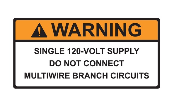
Article 705.82 has been deleted because the 120V supply may conflict with ratings and functionality of listed equipment. In particular, Article 705.82 was deleted as it was unnecessary in this section of code.
705.82 Single 120 Volt Supply.
Systems operating in island mode shall be permitted to supply 120 volts to single phase, 3-wire, 120/240 volt distribution equipment where there are no 240-volt outlets and where there are no multiwire branch circuits. In all installations, the sum of the ratings of the power sources shall be less than the rating of the neutral bus in the distribution equipment. This equipment shall be marked with the following words or equivalent:
WARNING
SINCLE 120 VOLT SUPPLY
DO NOT CONNECT MULTIWIRE BRANCH CIRCUITS
The warning sign(s) or label(s) shall comply with 110.21(B).
Also, the requirements for identification in Article 710.10 were revised for clarity. Inclusion of the article title was redundant and added confusion to the requirements. The phrase “or be grouped with other plaques or directories for other on-site sources” was removed based on equipment to comply with section 705.10. See below:
710.10 Identification of Power Sources
A permanent plaque, label or directory shall be installed at each building a building supplied by a standalone system at thepower source disconnecting means location, or at an approved readily visible location. The plaque, label or directory shall denote the location of each power source disconnecting means for the building or be grouped with other plaques or directories for other on-site sources. Where multiple sources supply the building, markings shall comply with 705.10.
On a side note, some changes were made to cable tie requirements. 690.31(C)(1) included changing the words “listed or identified” to “listed and identified for securement and support in outdoor locations” to ensure that cable ties are rated for outdoor securement.
690.31(C)(1) Single-Conductors.
Single-conductors shall comply with 690.31(C)(1)(a) through 690.31(C)(1)(c).
(a) Single-conductors in exposed outdoor locations in PV system dc circuits within PV arrays shall be permitted to be one of the following:
(1) Type PV Wire
(2) Single-conductors marked sunlight resistant and Type USE-2 and Type RHW-2
(b) Exposed conductors shall be supported and secured by one of the following methods:
(1) Cable ties that are listed and identified for securement and support in outdoor locations
(2) Straps, hangers or similar fittings or other approved means, designed and installed so as not to damage the conductor
(c) Conductors sized larger than 8 AWG shall be supported and secured at intervals not to exceed 1400 mm (54 in.).
As you can see, there weren’t any new labels added, but most of the labeling changes were either editorial – fixing small errors, simplified, clarified or moved to more appropriate locations. These and other changes will be more dramatic in the NEC2029 code, when all the chapters will be renumbered. As an example, in the NEC2029 code, Article 690 will be included in Chapter 18 “Energy Sources.” Major code book changes are on the way after NEC2026 is published.
Todd Fries is a product category manager of identification systems with HellermannTyton North America in Milwaukee, Wisconsin. He also serves on Code-Making Panel 4 of the NEC 2026 and was involved with the changes and additions discussed in this article.
HellermannTyton | www.hellermanntyton.us
Author: Todd Fries
Volume: 2025 September/October