


How to Mitigate Temporary Overvoltages in PV Plants


It is mandatory that solar power plants remain connected to power grids for a certain period to support them during fault events. However, under certain circumstances, these ride-through functions may exhibit delayed response or even misoperation of inverter, leading to temporary overvoltages (TOV) problems and equipment damages [1], [2]. Major scenarios of these phenomena include load rejection and ground faults, each posing unique challenges.
- Short Circuit Faults: When a single-line-to-ground (SLG) fault occurs, power on the faulted phase drops to zero. Because a grid-tied inverter typically acts as current sources, it increases the current on two healthy phases to maintain overall power balance, resulting in TOV.
- Load Rejection: When a part of power circuits with significant PV generation disconnects from the grid, it becomes an islanding system where solar output power exceeds the local loads, creating an imbalanced Generation-to-Load Ratio (GLR). During the short interval before solar inverters recognize the disconnection, TOVs can arise. Predicting Load Rejection Overvoltages in practical scenarios is complex. Overvoltage level positively correlates with GLR, but also varies due to specific inverters [3].
- Solution to TOV: Grounding switches (GW) offer a promising solution to TOV issues during islanding events. By providing an alternative path for fault currents, GW help discharge excess energy and force voltages to a desired level, therefore yielding benefits of fault current diversion, voltage regulation, and enhancing inverter performance.
Case study
One study considers the overvoltage issues resulting from the misoperation of inverters in a solar PV project (Fig. A). The project includes nine (9) 3.3-MW inverters. The surge arrester on the MV side is modeled by 29 kV-MCOV and 10 kJ/kV MCOV arrester. The project is modeled on PSCAD/EMTDC 5.0.

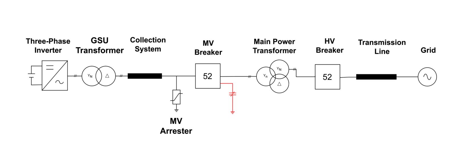
Figure A. Single-line diagram of the solar PV system
In this study, three test cases were analyzed for TOV: load rejection, SLG, and 3LG fault scenarios. In SLG and 3LG fault cases, the faults are induced at 2.0s and the MV breaker opens after several cycles. In the load rejection case, the MV breaker opens at 2.0s.
- Load Rejection Result
Without the GW, the inverter experiences a significant voltage increase to nearly 1.9 pu, lasting for 0.4s. The energy from the feeder arrester exceeds the allowable value (290 kJ), posing a risk of equipment damage. Conversely, with the GW, the inverter experiences a brief overvoltage lasting only two cycles, quickly decreasing to nearly zero. The energy from the feeder arrester is less than 80 kJ (below the limit). These demonstrate that the GW worked as expected. The inverter voltage and feeder arrester energy responses energy are depicted in Fig. B and Fig. C, respectively.
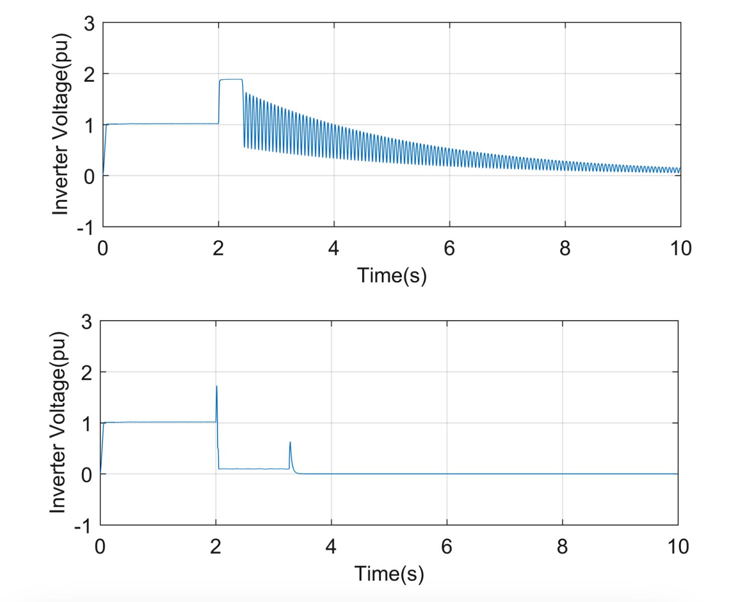
Figure B. Voltage of inverter in case of LRO without (top) and with (bottom) GW
Figure C. Feeder’s arrester energy in case of LRO without (top) and with (bottom) GW
- Single-Line-to-Ground Fault Result
Without the GW, the feeder arrester energy is around 170 kJ, below the limit. However, considering potential circuit variations, the safety margin may not be sufficient. In contrast, with the GW, the energy from the feeder arrester is less than 4 kJ. This demonstrates the GW enhances the safety margin by more than an order of magnitude.
- Three-Line-to-Ground Fault Result
In this case, the GW enhances the safety margin by over two orders of magnitude. The feeder arrester energy is less than 80kJ (< 290 kJ limit). Without a GW, the arrester energy is over 1000kJ exceeding its limit.
Analysis
In these case studies, the inverter trips according to the inverter protection setting (inverter trips if the voltage magnitude is higher than 1.3 pu for 0.4s). To examine the impact of the protection setting modification, an extra test case was conducted for the load rejection scenario in which the high voltage ride through (HVRT) modification is to have 1.3 pu for a shorter duration of 0.2s. The result shows that the overvoltage peaks at 1.9 pu for 0.2s. The feeder arrester energy exceeds 600 kJ, significantly higher than the permissible limit. This shows that, while the adjustable protection settings have no clear benefit, they could further impact the inverter’s ability to remain operational during the HVRT. Therefore, implementing a GW is an effective way to guarantee the safe operation of electrical equipment.
Conclusion
TOV of PV systems under faults can damage the PV system and interconnected electrical equipment. The dilemma is that the ride-through setting, which affects TOV incidents, needs to be set high enough to comply with the HVRT requirements. Also, modification of HVRT setting might not mitigate TOV, and can even worsen situations.
To eliminate the potential confusion arising from the delicate balance between riding through voltage fluctuations and tripping, a viable solution is to induce a drastic drop in collection feeder voltages. Implementation of GW will eliminate the confusion and help inverter manufacturers keep the HVRT wide enough to support power grid reliable operation under disturbances.
Tuan Ngo (Ph.D., P.E.) and Tuyen Vu (Ph.D., P.E.) are with Intelligent NRG Solutions (INS Engineering). INS offers engineering solutions in system designs, modeling, and studies for power transmission, distribution, and renewable energy systems including solar, wind, and energy storage systems. [email protected] | (941) 222-0155
Intelligent NRG Solutions LLC | www.inrgx.com
|
[1] |
P. Barker, "Overvoltage considerations in applying distributed resources on power systems," 2002 IEEE Power Engineering Society Summer Meeting, 2002. |
|
[2] |
M. Ropp, "Inverter grounding and overvoltages," IEEE PES General Meeting, 2014. |
|
[3] |
A. H. S. C. J. C. T. W. B. Z. a. M. R. A. Nelson, "Experimental Evaluation of Load Rejection Over-Voltage from Grid-Tied Solar Inverters," IEEE Photovoltaics Specialists Conference (PVSC), 2015. |
Author: Tuan Ngo, P.E. and Tuyen Vu, P.E.
Volume: 2023 November/December