

Providing for Wind or Solar Power Plant BES Safety and Reliability


 As an engineer, you're used to figuring things out. If you're an engineer in the wind power industry, you're also used to dealing with the numerous, and sometimes onerous, regulatory changes thrown at you every few months. 2018 brings some challenges to your job, courtesy of the Federal Energy Regulatory Commission (FERC) and the North American Electric Reliability Corporation (NERC). Luckily, we're here to help.
The U.S. Congress wants a safe and reliable Bulk Electric System (BES) with renewables, and FERC and NERC have been providing Orders and Standards to meet those objectives, and there is an upside for renewables; but first renewables must rise up to "new-challenges" so they can realize the upside with the rest of the BES.
THE CHALLENGE
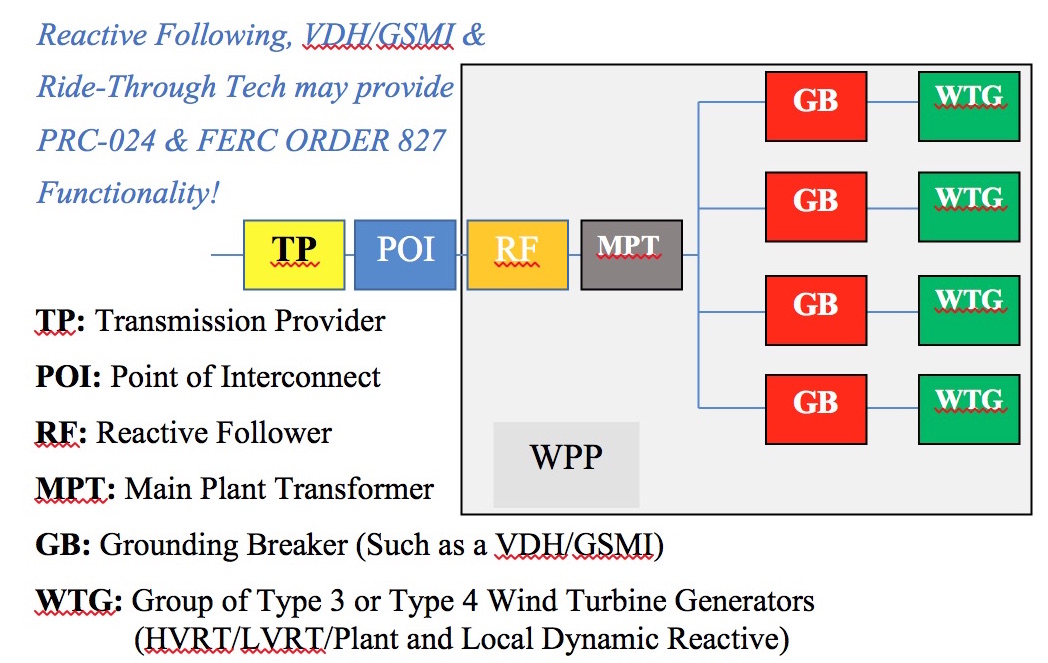
Your mission is to provide for meeting the old and new Point of Interconnection (POI) requirements found in FERC Order 827, NERC standards PRC 024-1-2, and the various other PRC, MOD and VAR standards. Let's get technical; with regard to the Bulk Electric System - with Rated Voltage greater than or equal to 100KV, and Rated Power greater than or equal to 100MW - it may be achieved with:
- Reactive Following
- High Voltage Ride Through
- Low Voltage Ride Through
- Detailed simulations of the wind power plant (WPP) or solar power plant (SPP) with PSCADTM
- Including grounding breakers, such as a VDH/GSMI, at each feeder
FERC Order 827 means that wind generators must now provide "dynamic" reactive power. New plants can adjust to the new standards, but what about the older wind power plants that were built with this exemption in mind? More importantly, how can you redesign your company's aging wind plant to meet the newer FERC orders?
MORE THAN JUST "RIDE THROUGH"
 Wind turbines need a system to help them stay online through power interruptions, or "ride through" the event while providing dynamic reactive support during the disturbance. However, "Low voltage ride through", "High voltage ride through", and "ride through with zero voltage capacity" will not, by themselves, provide the functionality to meet the new FERC orders and NERC standards. WPPs and SPPs are constructed with collection systems; plant components like the main transformer, generator step up transformers, junction boxes, branch, string, and homerun cables, all include an impedance (Z) within the collection system. When it comes to meeting the FERC and NERC standards, overcoming the "Z(s)" is your problem. "Z(s)" come in many forms, as presented in the equations below:
- Zelement=[Relement+jXelement]
- Ielement=Ire+JIim
- S=PWTG + jQWTG
- S=VI*
- VMPT=VPOI + (IMPT* ZMPT )*OLTC*Ratio
- VHomerun_cble=[IHomerun_cble*ZHomerun_cble]+VMPT
- Vbranch=Ibranch *Zbranch+VHomerun_cble
- Vwtg=Igsu*Zgsu + Vbranch
- Vwtg_imbalance=Vwtg * Phase_Imbalance
Equations 1 through 9 are presented to calculate the voltages within the collection system of the power plant. Think of them like tree, where you start at the Trunk (5) or Main Plant Transformer (MPT) at the Point of Interconnection (POI), and work your way back to the furthest leaf, or wind turbine or solar generator (9). The idea is to calculate the voltage with the collection system for a given POI voltage (with a Real and Reactive power flow through the POI). The standards include dynamic conditions, so we need to include control systems and other dynamic elements into our considerations, where many calculations are needed to provide a more complete picture. To gain better insight into the plant, we need a time domain analysis tool like PSCAD.
WHY PSCAD?
PSCAD uses time domain/time step simulation in the microsecond range (with combined Power System Simulations, the control system, and control logic) to provide engineers an animation of the performance of the WPP or SPP. This lets the engineer "see" an ideal of the dynamic constraints that appear during a disturbance, or contingencies on the power system. With the Control System coupled to the electric power system, PSCAD can use reduced order models to simulate constraints within the plant; this makes it easier to determine the type of ride through and dynamic power controls needed to meet relevant FERC and NERC targets.
 CONSTRAINTS
The constraints measured in PSCAD are dynamic and transient - they appear and disappear. Within the plant, constraints may be physical and/or regulatory, and are generally measured in different locations, catalogued, and checked against operating requirements as dictated by FERC and NERC. At the end of the day, however, constraints are compared against the interconnection agreement. A technique called Reactive Following, used to assess the constraints, provides plant owners several safe and reliable methods to exceed their Large Generation Connection Agreement (LGIA) compliance, with both the Transmission Provider (TP) and electric reliability organization (ERO). Your interconnection agreement requires a certain amount of reactive power support to the transmission system. Reactive Following will help your facility meet FERC Order 827, NERC PRC-024, and any other requirements for non-synchronous generators. It's all very technical, and can be confusing even for a seasoned engineer, but with the right tools, you can find the optimized solution for your company.
Miles Downing and Thomas Wilkins are both independent Power Systems Engineers who for the past 19 years have worked in the power systems industry with a focus on renewables. Miles Downing is a registered professional engineer with a Master Degree from Portland State University in Power Systems Engineering, who worked with Bonneville Power Administration and with EDF Renewable Energy. He is currently based out of Vancouver Washington. Thomas Wilkins has a BSEE from San Diego State University and is an inventor with several power systems related patents, and has worked both nationally and internationally on interconnection related matters for renewables where he is based out of Henderson Nevada; where both Miles and Tom maintain a website called Rfwind.com
RF Wind | www.rfwind.com
Volume: 2018 January/February