

Practical Solutions for In Service Pitch Bearing Issues


Multiple wind turbine failure databases reveal that pitch bearings are one of the subassemblies with the highest failure rates, and largest contributors to overall downtime. The average life of a pitch bearing varies by manufacturer, turbine, and site operating conditions. Given the current design constraints, as the diameter of wind turbine rotors increase, and projects are placed in more turbulent sites, failure rates are expected to rise.
The pitch bearing allows for variable pitch position of the blades to maximize energy yield, and for load transmission from the blades to the hub. The most common pitch bearing arrangement used in wind turbines is the double row 4-point contact bearing, also known as an 8-point contact bearing. Similar to bearings found in the gearbox, the pitch bearing is comprised of outer and inner raceways, a cage, and rolling elements. Cage designs vary, and include individual plastic spacers, and single or multi piece split cages. The pitch bearing is equipped with two seals to contain the grease within the bearing, and prevent the ingress of foreign particles. (Figure 1 below).

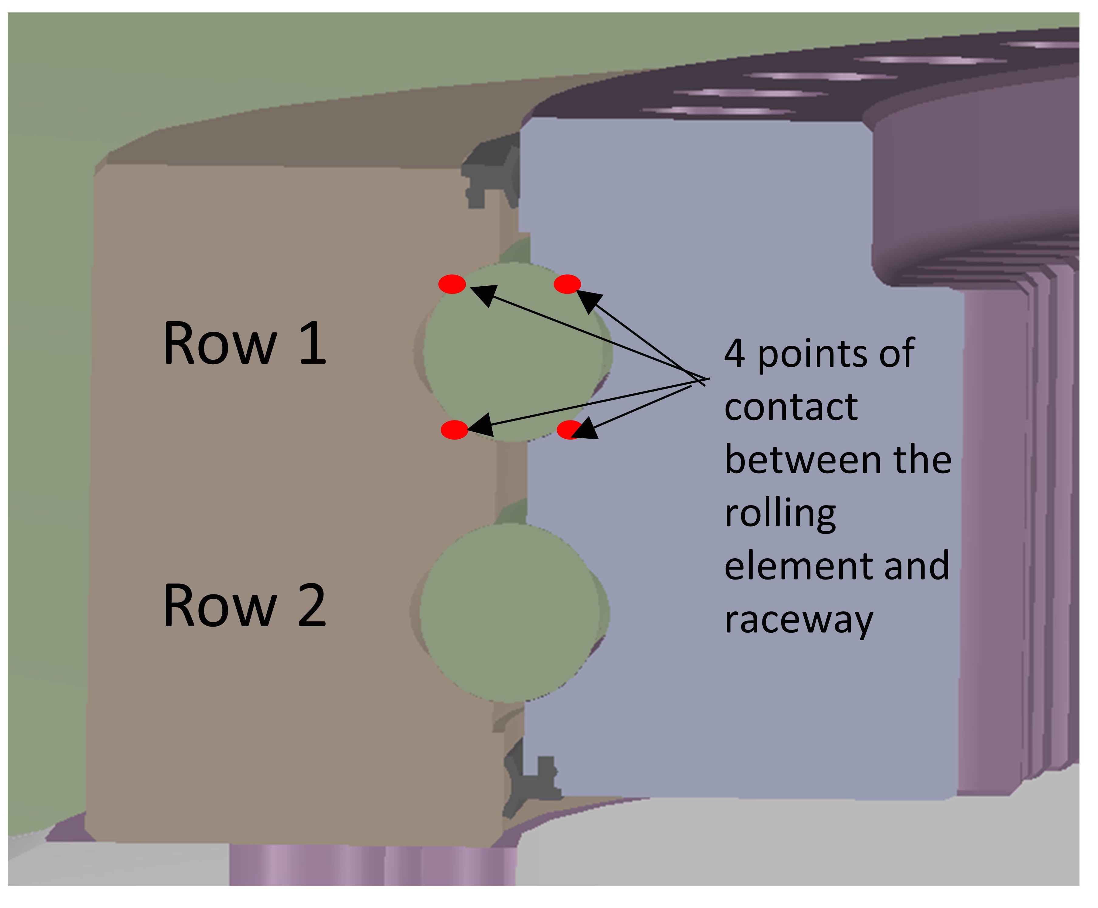 WIND_InSight Analytics Solutions_Figure1: Figure 1. The pitch bearing connects the blade to the hub and allows for variable pitch position of the blades. The most common pitch bearing arrangement utilized in wind turbines is the double row 4-point contact bearing, also known as an 8-point contact bearing.
Common Failure Modes
In service, the pitch bearings rotate in short intermittent sweeps, and can spend extended time with little to no rotation. Due to slow rotational speeds, pitch bearings operate in boundary lubrication, which can result in more rapid accumulation of surface damages compared to bearings that operate with sufficient film thickness. Extensive root cause analysis work identified common causes of failures, including ellipse truncation, cage wear and surface fatigue cracks originating at stress concentrations, and quality issues from poor induction hardening (summarized in Table 1).
The cause of ellipse truncation is typically due to deflections in the bearing raceway, due to insufficient stiffness under normal operating conditions or extreme loading events. This results in high loads at the edge of the raceway, which leads to macropitting.
Another common failure mode is outer ring cracking, usually located in the vicinity of a stress riser such as a through hole or other feature. This cracking failure mode is normally isolated to a specific bearing design or supplier. If allowed to continue operating, the crack can eventually progress into the hub and cause other system failures.
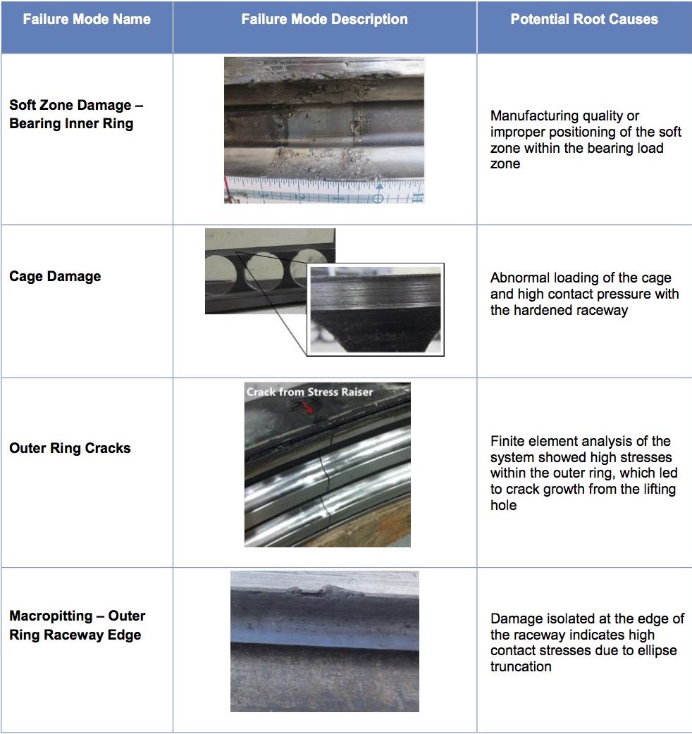
WIND_InSight Analytics Solutions_Table 1: Table 1 below. Summary of common pitch bearing failure modes as identified by numerous root cause analysis investigations.
Failure Detection
The current industry standard for detecting pitch bearing issues is the turbine controller alarm system and grease analysis. The turbine control system alarms once the failure has progressed to a state of catastrophic or functional failure. Grease analysis can provide more advanced warning by allowing the reliability engineer to investigate the size, shape, and type of wear particles present in the grease. With this information, an assessment of the bearing health and severity of damage can be determined. However it is difficult to ensure the sample collected from the bearing is representative of the entire bearing and there are no hard and fast guidelines to easily interpret test results. Some wind farm owners and operators have successfully detected pitch bearing damage through analyzing SCADA parameters, such as pitch motor current, pitch ram pressure, and pitch tracking errors. This is more complex, since anomalies can be due to the pitch adjustment mechanism, rather than the actual bearing.
Additional techniques for pitch bearing health monitoring are under development and in the early stages of adoption within the industry. These include vibration assessment and borescope inspection. Portable vibration equipment can be used to capture data on the pitch bearing during constant speed pitch from 0 to 90 degrees. This data is analyzed for the presence of pitch bearing fault frequencies. This method has the potential to provide owners and operators with more advanced warning than current industry methods.
Depending on the bearing design, a borescope inspection may be possible through the grease zerks, or other ports located on the pitch bearing. Typically, a 4mm borescope is recommended for the inspection, due to the small port size and limited space within the pitch bearing. Borescope inspection has the benefit of visual damage confirmation, allowing for a more proactive approach to replacement as opposed to the strategy of replacing upon functional failure.
Practical Field Solutions
Changing the grease type, re-lubrication quantity, and frequency can be performed on pitch bearings to address wear related failure modes. However, failure modes such as macropitting from ellipse truncation or outer ring cracks require a different corrective action.
Innovative solutions are now coming to market to help extend the life of in-service pitch bearings. Applying a compressive stress to the outer ring can eliminate the formation and propagation of cracks in the pitch bearing. FEA analysis of the hub and pitch bearing can identify the levels of stress that contribute to crack propagation. Then the amount of outer ring compressive stress required to reduce the von Misses stress at the crack initiation point can be determined. Figure 2 shows a pitch bearing field retrofit that resulted in a 21% stress reduction. This corrective action hardware can be installed uptower on an in-situ bearing. It is recommended to preform field verification testing utilizing strain gauges to measure the strain before and after compression hardware installation, as well as during turbine operation. The measured values need to correlate with the predicted strain values. The outcome is a pitch bearing that operates at a reduced stress, thus extending its life.
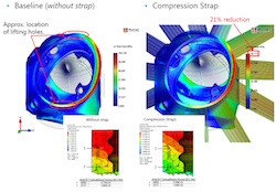
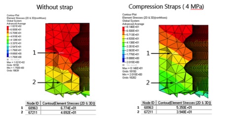
WIND_InSight Analytics Solutions_Figure2: Figure 2. Innovative pitch bearing field retrofit solution that can be installed uptower on an in-situ bearing. The outcome is a pitch bearing that operates at a reduced stress, thus extending its life.
 Becki Meadows is a consulting engineer with Romax InSight. She graduated from the University of Michigan with a degree in mechanical engineering and went directly to work as a field engineer for General Electric's Power Generation division, inspecting and repairing steam turbines and generators at small/medium power plants across the country. During her five years with GE, she was trained in statistics and process management, which lead to a career as an independent consultant/trainer and co-author of a book on how to use statistics to effectively manage business. Prior to working at Romax, she worked as a senior engineer at the National Renewable Energy Laboratory (NREL) completing wind resource assessments for the federal wind program and cost of energy modeling for distributed energy and offshore wind projects.
 Jason Shapiro is the engineering manager for the Romax InSight field team. He started his career in the wind industry in 2008 working for a major turbine manufacturer as a drivetrain engineering specialist. His expertise includes bearing and gear failure analysis, reliability engineering, lubrication analysis, supplier audits, and fieldwork. Jason has a mechanical engineering degree from the University of Colorado and lives in Boulder, Colorado.
Romax InSight | www.romaxtech.com
Volume: 2017 May/June