

Solving the Challenge of Building a Leak-Proof Array
Share


Building a PV array to face the diverse environmental challenges of each site such as wind, moisture, and hurricanes can be very challenging but is possible with the use of simple design and quality materials.
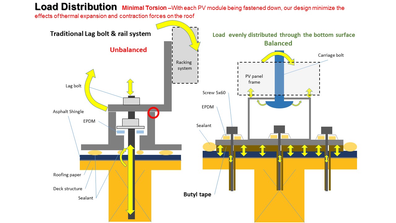 Securing each PV module with multiple fasteners can spread the mechanical load evenly throughout the roof surface and, more importantly, alleviates the torsion applied to a roofing system due to thermal stresses; the thermal contraction and expansion of an array, which is primarily built with aluminum containing a high coefficient of thermal expansion, has the most movement on top of a roof. One design, being that the rail is the module frame, mitigates such effects that a minimum distance between adjacent rows can be as low as 3mm (1/8”). 4” wide mid and end clamps distribute the clamping pressure on a larger surface of the PV panel frame.
The next step is the perfect sealing of each attachment point with butyl tape. Butyl was first developed in the early 1930’s and today is the most important material for the inner linings of tubeless tires. Among its traditional applications are pool linings and flexible flashing for construction.
Butyl rubber’s unique combination of barrier properties, high damping, resistance to ozone, weatherproofing, and heat aging make it the ideal choice for many construction applications. For instance, butyl rubber is commonly added to asphalt compositions in the manufacturing of roofing materials to improve the weatherproofing and low-temperature properties of the asphalt.
Butyl flashing provides impermeability and elasticity. It is easy to mold, yet highly resistant to punctures. It retains its elasticity and strength when exposed to service temperatures between -40°F and 248°F. Even with extreme fluctuations in temperature, butyl tape allows for expansion and contraction while preventing moisture from passing through. It has an effective life of 20+ years and is resistant to aging weather, mildew, acids, alkalis, and salts. It is common knowledge that no matter how the attachment of a PV array is achieved, the ultimate sealing point is exactly at the penetration in the roofing paper, where a lag or fastener gets attached to the frame or roof sheathing. This is conventionally accomplished with the use of sealants. Typical sealants have an upper service temperature between 160°F and 200°F. Butyl performs at temperatures up to 248°F, which makes it longer lasting due to heat distress.
Diligent product engineering and laboratory testing is imperative. Tests can include; extreme conditions of constant UV light, temperatures up to 145.4°F, humidities at 50%, and every two hours, a water spray inside the Carbon Arc machine. The specimens should be monitored throughout the testing time and evaluated to discern quality and performance.
The code is simple and objective as far as flashings for the PV supports. It states that roof-mounted PV system flashings must be installed in a manner that prevents moisture from entering penetrations through the roof plane (IBC & IRC 2012). The current suggested guideline by the National Roofing Contractor Association (NRCA) for the installation of flashings for PV system stanchions on a steep-slope, asphalt-shingle roof recommends the metal flange be applied underneath the roofing paper (under the upper underlayment) for proper water shedding. It is the only way to create a proper water shedding flashing mechanism. However, this can only be accomplished simultaneous with the installation of a new roofing system, and not on a retrofit of a PV system installed above an existing roof; which is the majority of installations in the US.
Even though the roofing paper is called a secondary layer to protect the roof decking, it is more accurately described as the first layer, not only because it’s the first one to be applied, but if the roofing material or anything else fails, the roofing paper or felt is the layer that will protect the roof decking from moisture intrusion. With this in mind, the removal of nails to allow for an “adopted” proper placement of a metal flashing, actually is the same as creating a hole on the roofing paper where moisture will find its way in.
The Center for Environmental Innovation in Roofing doesn’t recommend water shedding flashings on the roof where there is potential ice damming such as eaves, or overhangs, and all around the PV array. It is recommended to use waterproof flashings in areas where ice damming may occur.
The other concern from installing metal flashing between roofing shingles is the effect on the warranty of the roofing material itself. The separation of the shingles can be treated as a failure to seal the roof (blow-offs), which will normally drastically reduce the warranty from the roofing manufacturer; for instance, the warranty on a general aniline and film (GAF) roofing product was reduced from 50-years to 15-years roof warranty for the failure to seal. The roofing manufacturers will become more involved as far as recommendations for the installation of PV systems on top of their roofing products based on future codes yet to be adopted.
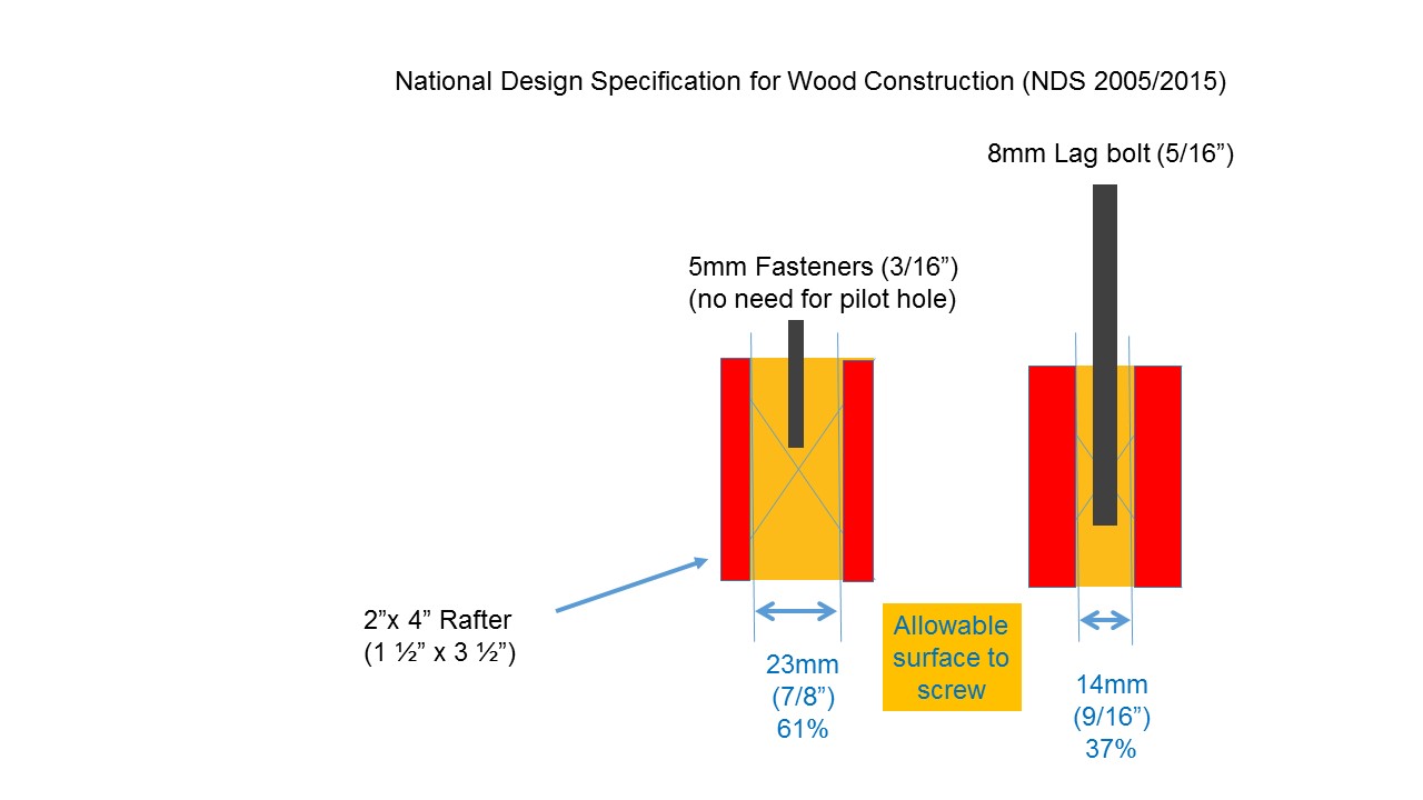 The application of butyl tape flashing guarantees 100% waterproofing on low- and steep-slope asphalt roofing applications while still fully complying with code requirements. It is fastened with 5mm stainless screws and doesn’t require a pilot hole. By code, the area for the attachment to the rafter is wider when compared to the 5/16” (8mm) usual lag bolt (National Design Specifications (NDS) 2015). This allows the installer to easily meet code without the risk of splitting a rafter. According to NDS 2015, when the attachment on the rafter is parallel to the grain, the minimal, clear distance to attach a bolt or screw to secure the PV attachment from the edge of the rafter is 1.5 X D (D=shaft diameter) = 7.5mm (5mm screw) versus 11.91mm for a 5/16” (8mm) lag bolt. This means with the 5mm fastener, the installer gets a wider area to fasten in order to meet the NDS code. Installation time savings is another benefit with this system. The array installation would normally take 2 hours with a rail-based system. Once the installer got to understand the process, the time for similar array assemblies dropped to 40 minutes.
Milton Nogueira is a former board member of the Northern California Solar Energy Association and holds a C-46 California contractor’s license. Milton earned his bachelor of science in Mechanical Engineering from the University of Santa Catarina in Joinville, Brazil. He has been an advocate of solar energy for nearly three decades and has extensive experience in photovoltaic system design and sales. He joined Roof Tech in their first U.S. operation and is their senior business development manager.
Roof Tech, Inc. | www.roof-tech.us
Volume: September/October 2015