


Aimed at the Sun: Solar tracking systems for CSP


 For any solar energy system, there are obvious benefits to having the collectors aimed directly at the sun as it follows its daily and seasonal cycles. For relatively small projects, such as photovoltaic (PV) systems mounted on residential or commercial rooftops, the cost and complexity of a full-fledged solar tracking system can outweigh potential improvements to efficiency and output. However, as systems become larger, the case for keeping collectors continuously aimed at the sun becomes far more compelling.
For concentrated solar power (CSP) systems, where the basic objective is to collect solar energy from a large area and concentrate it onto a much smaller target using mirrors or lenses, accurate solar tracking is critical. In such projects, closed-loop control systems that employ position sensors can offer significant improvements to the accuracy and efficiency required of these systems.
Parabolic troughs
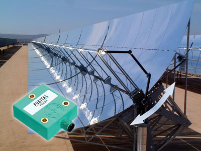
A popular approach to CSP is the parabolic trough design. Here, sunlight striking a long parabolic mirror is reflected onto a pipe that’s located at the focus of the parabola. A heat transfer fluid (typically thermal oil) is heated as it moves along the pipe, then flows to a heat exchanger where its thermal energy is used to boil water for a steam turbine. The energy-collecting efficiency of a parabolic trough system clearly depends on having most of the solar radiation reflected accurately onto the heat-collecting pipe.
For most systems, this is achieved by orienting the troughs in a north-south direction, then tilting the mirror/pipe assembly along its axis so that it follows the sun as it moves from east to west across the sky. Daily and seasonal changes in the elevation of the sun above the horizon cause the heated zone to shift along the axis of the pipe. However, since the mirror/ pipe assembly is typically much longer than it is wide, the loss of efficiency is relatively minor.
Building a solar tracking system for a parabolic trough installation is relatively straightforward. Motion is around a single axis and, while the requirement to rotate a large and unwieldy structure through an arc of almost 180° is not trivial, the motion is slow and regular so that the power requirements are quite modest. Control systems responsible for guiding the motion of the trough assembly often take advantage of the fact that the sun’s trajectory is very well defined. An algorithm in the control system will calculate the correct orientation angle for the time of day and year, while inclinometers (tilt sensors) mounted on the moving structure measure the actual position of the receiver and provide feedback to the system.
Solar power towers
Another important CSP design is the tower/heliostat system. Here, a large number of moveable mirrors—termed heliostats—reflect solar energy onto a heat receiver mounted on a tall tower. Tower/heliostat systems lend themselves well to large-scale developments, such as the Ivanpah Solar Electric Generating System in California, which is projected to produce up to 377 megawatts of electric power and will be the largest solar thermal power tower system in the world once complete (see http://ivanpahsolar.com).
Solar tracking systems for tower/heliostat installations, however, present some significant challenges. For one, the required level of accuracy is high. For a heliostat located 300 meters from the heat receiver, the aiming accuracy must be within as little as +/- 0.1 degrees. This ensures the reflection of the sun’s image on the receivers fall within one meter of its intended position. Another challenge is the scale of the system. For a large development, there can be tens of thousands of heliostats.
Moreover, each heliostat mirror must be separately controlled in two dimensions to track the sun’s daily and seasonal movement across the sky—following a trajectory that’s uniquely tailored to take into account the relative position of the heliostat and the receiver unit. And, beyond keeping the heliostats pointed in the right direction to reflect solar radiation, the control system and actuators are often required to move the mirrors into a “parked” position to avoid damage during extreme weather events.
Control systems
There are two basic approaches to control systems for solar tracking: open- and closed-looped designs. In open-loop systems, the controller sends signals to actuators so that they move the reflectors along a pre-determined trajectory. Since the sun’s motion is entirely predictable, this approach can work quite well. However, if the supporting structures are distorted or shift their position due to settlement of their footings, aiming accuracy is reduced and overall system efficiency will suffer. Periodic re-aiming of the heliostats is necessary to correct these errors.
With closed-loop control systems, the controller receives feedback on the exact orientation of reflecting mirrors, either from position sensors mounted on these components or by optical aiming methods. Feedback of real-time orientation or light-aiming data to the control system will improve tracking accuracy, albeit at the expense of increased system complexity.
Equipment mounted on reflector systems, such as position sensors and motion actuators, need to be accurate and highly durable. Temperature variations in the desert areas (where CSP installations are typically located) are far more extreme than most industrial settings. Dust, moisture, and prolonged exposure to UV radiation are added threats. For tower/heliostat systems, the large number of heliostat units typically used means that costs add up quickly. To ensure projects and project success, low unit cost for components in the solar tracking system is important to the overall economic viability of these systems.
Christian Fell heads FRABA Inc., the US unit of FRABA Group N.V., which is an international manufacturer of position and motion sensors.
FRABA Inc.
www.fraba.com | www.posital.com
Author: Christian Fell
Volume: November/December 2013