Page 12 - North American Clean Energy March April 2015
P. 12
wind power
Remote Offshore Sensing Resources
An alternative to met masts
By Mark Pitter & Alex Woodward
Figure 1.
Figure 2.
Figure 3.
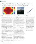
REMOTE SENSING ON FLOATING OFFSHORE PLATFORMS, such as he nature of buoy motion is such that very little movement Figure 1. CW lidar wind measurement stability in
buoys, barges and ships, provides a cost-efective alternative occurs over the 20 milliseconds (ms) required for each line-of- relation to static tilt and wind direction (Examples
to expensive foundation-mounted ofshore wind monitoring sight measurement. And, even over the one second required to of available loating lidar devices by manufacturers
towers for wind resource assessment. It’s unlikely that measure at each height, motion is limited.
to measure wind parameters ofshore, include:
foundation-mounted ofshore meteorological masts will ever his core technical speciication of CW lidar delivers results Babcock’s FORECAST (as shown in Figure 2);
be viable in water depths of over 100 feet; however, loating as shown in Figure 1. he worst-case scenario for the buoy- SeaRoc’s SeaZephIR; Fugro’s SeaWatch; EOLUS;
platforms (depending on their design) can be deployed in mounted CW lidar tested: experiencing period pitching
FloatMast; and Fraunhofer’s Wind Lidar Buoy).
almost any water depth.
or rolling of 10° or less, which is an under-read of around
As loating wind turbines in deep, ofshore waters start 0.75%. Nonetheless, platforms such as spar and tension leg Figure 2. Babcock’s FORECAST loating wind
to come online in the North American wind market, issues buoys don’t exhibit enough motion to bias the wind speed lidar, driven by Continuous Wave lidar ZephIR
related to the collection high-quality, bankable, hub height measurements to any appreciable amount, as they’re typically 300. As one example, the Babcock FORECAST is
wind data becomes ever more relevant.
limited to periodic motion of less than 5°—leading to a bias a low-motion spar buoy, which reduces motion to
of less than 0.25% (when the results are averaged around the a level where compensation (other than yaw for
Weighing the costs
wind rose).
wind direction) is unnecessary to achieve excellent
he use of a remote sensor presents signiicant opportunities Although it’s possible to stabilize a lidar to some extent by accuracy and precision. (In a recent ofshore trial
for up-front cost savings in any anemometry campaign, using a mechanical gimbal, this has never been found to be at Gwynt Y M̂r, in the Irish Sea of the north
especially when compared to traditional, more expensive
necessary for buoy-mounted CW lidar deployments.
coast of Wales, UK, regression parameters of R2 =
met mast methodology. However, these devices are subjected 0.990 and a gradient of 1.006 were achieved at a
to motion. If not fully understood, this could increase the Final thoughts
measurement height of 90 m, compared to the mast
uncertainty connected to the measurement, making the In conclusion, it can be seen from simulations and ofshore at Gwynt Y M̂r as shown in Figure 3.)
solution unviable. It could also negatively ofset any potential trials that the 10-minute averaged wind speed recorded by
capital expenditure (CAPEX) savings caused by measurement CW lidar is very resilient to the presence of the type of motion Figure 3. Herein, the lidar and mast were
uncertainty, impacting the lifetime of the wind farm.
experienced by a range of buoy designs—even when no separated by 260 m. At the time of publishing,
Buoys are primarily the device type chosen for mounting mechanical stabilization or software compensation is applied.
system availability has been 100% and data
remote sensors in loating ofshore applications. hey typically Yaw is easily compensated for by using a compass to availability has been greater than 99% at all
exhibit translational (surge, sway, and heave) and rotational determine the actual CW lidar bearing at the time of the measurement heights.
motions (pitch, roll, and yaw), and all of these motions have measurement. Translation motions tend to average to zero
the potential to adversely afect the measurement of the wind over 10-minutes, and do not degrade the results.
vector.
Floating CW lidar, therefore, has the real opportunity to
replace meteorological met masts and ixed platforms, as well
Deining the devices
as existing infrastructure deployed with remote sensors. And,
here are currently two types of inance-grade (DNV GL Stage they can do so for a fraction of the current cost delivering
3) wind lidars on the market: Continuous Wave (CW) and the lowest cost of energy possible as a wind measurement
Pulsed. hey are both termed Doppler lidar—that is, they resource.
sense the Doppler shift of the received light and use this to
calculate the wind parameters.
A full technical paper detailing all studies and trials to date,
CW lidars are deployed on 85% of buoy manufacturers entitled “Performance stability of ZephIR in high motion
loating lidar systems today, and measure the wind speed
environments,” is available by request ([email protected]).
at user-deined heights in a sequential fashion. All of
the available laser energy is focused at the user-deined Mark Pitter is a scientist and ofshore applications leader and Alex
measurement height, leading to a high carrier-to-noise ratio Woodward is the head of product development, both at ZephIR
(CNR). Consequently, very high line-of-sight velocity data Lidar.
rates of 50 Hertz (Hz) occur. his leads to 50 line-of-sight wind
data points being acquired during a one second scan at each ZephIR Lidar | www.zephirlidar.com
height.
12 nacleanenergy.com
MARCH/APRIL 2015