


Identifying Faults in Wind Power through Electrical Signature Analysis


Every wind turbine operates on a rotating electrical and mechanical system. Wind farms employ one of two generator systems, either Doubly Fed Induction Generator (DFIG) or Singly Fed Induction Generator (SFIG). Most newer turbines tend to use DFIG, but both can suffer two major electrical faults: wye ring failures in the rotors; and, transformer failures due to high gassing. While there have been a few theories as to the root-causes of these failures (along with a number of approaches to mitigate, or ignore the fault), Electrical Signature Analysis (ESA) data has identified the possibility of ferroresonance in the transformers or Sub-Synchronous Resonance (SSR) in the generators; and that they occur in tandem.
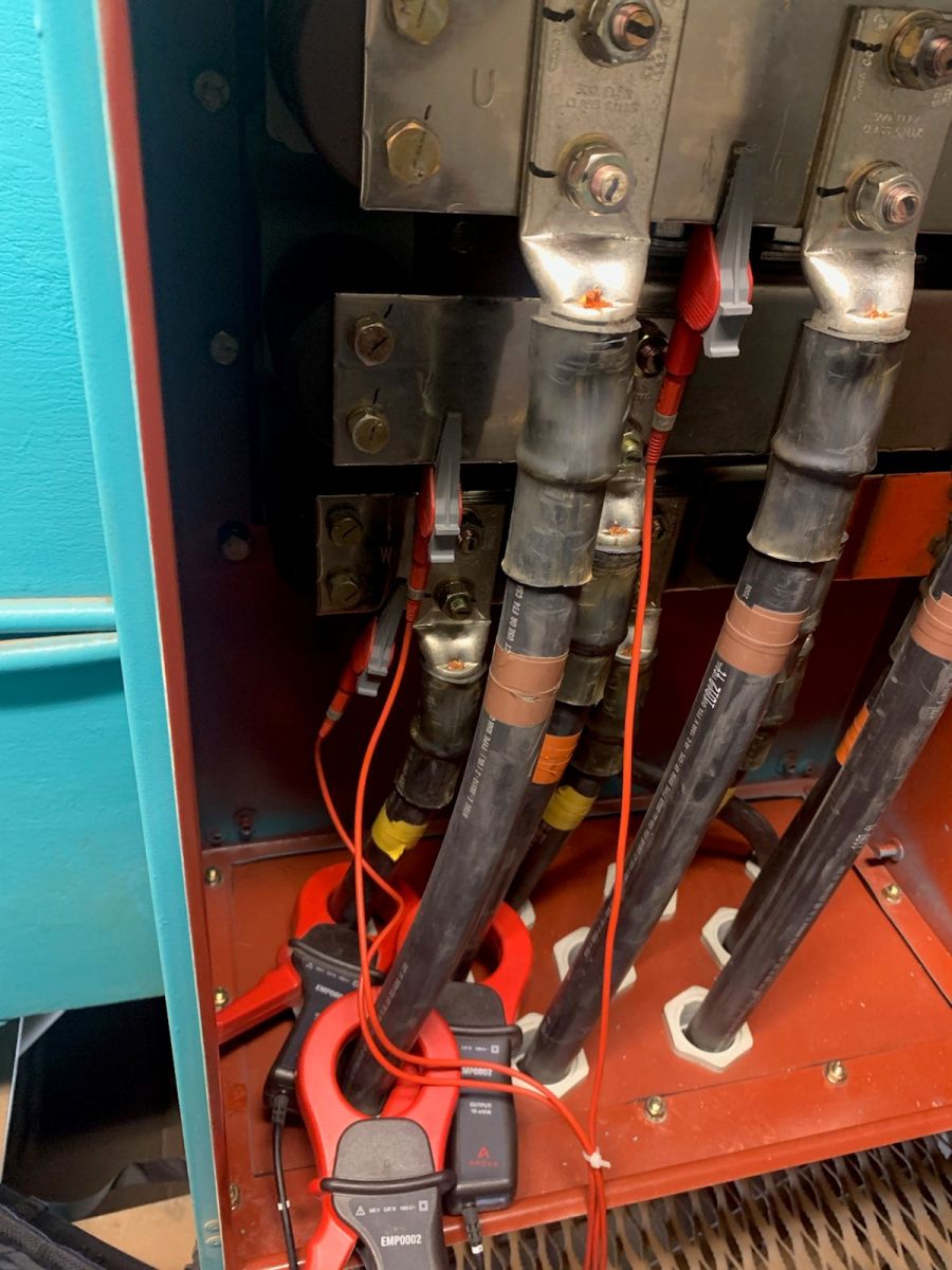 The application of ESA in wind generation involves the collection of both voltage and current between the tower's transformer and generator stator. For the values necessary to identify these conditions, a high sample rate is required as well as high resolution for spectral analysis. When the transformer is downtower, the data is normally collected at the base of the tower. The first case in question involves data collected at the generator connection box uptower (Figure 1) using a 3:1 CT ratio (further away from the rotor control).
(at right) Figure 1: Current clamps and voltage clips connected in the generator connection box.
Voltage and current were collected across 240 seconds, starting with the close of CB1 in order to observe conditions following the close of K1. Data was collected at a wind speed of 5.8 m/s (13 mph) with gusts to 8 m/s (18 mph) at 52oF, which has the generator on the lower end of the tower power curve and the control compensating for power factor through output to the rotor. The Voltage and current associated with the start and 240 seconds are found in Figure 2.

Figure 2: Voltage (bottom) and current (top) on the generator across 240 seconds starting with the close of CB1(1) then K1(2) - represents all three phases.
In Figure 2, the turbine is yawed into position, comes up to speed, and CB1 closes (1) followed by the closing of K1 (2) at which point the current spikes and oscillates before settling down and increasing. In the case of the current in this image, the variations are due to wind gusts. The spectra were evaluated at each point, as noted in Figures 3 and 4.
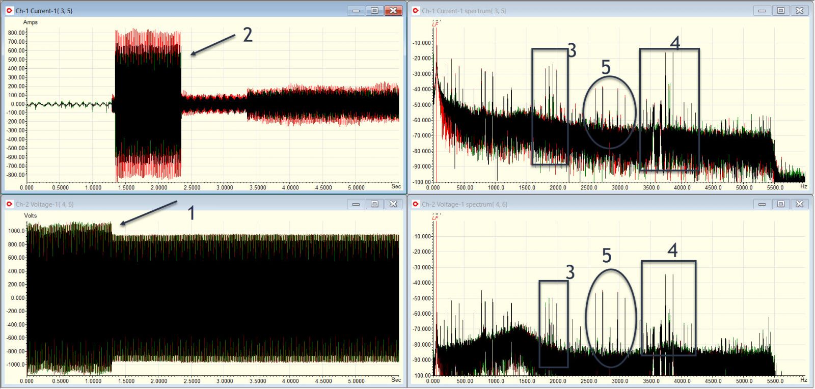
Figure 3: Closer view of after CB1 closes (1) and the oscillation immediately after K1 closes. The firing frequency of the DFIG rotor inverter (3) and a harmonic (4) exist as well as a resonance between (5).

Figure 4: At the sample location 3 of Figure 2, the levels drop as shown in the primary inverter frequency (1), harmonic (2), and resonance (3).
As has been observed in over 2500 datasets of DFIG and SFIG generators, the rotor inverter frequency and harmonic and the resonance frequency vary based upon the wind speed, load, and distance the wind farm is from larger loads. The conditions in Figures 2, 3, and 4 relate to effects with the transformer, as current appears to have a higher value in dB. A view of the rotor voltage and frequency (Figure 5) on the rotor of a similar turbine at 4.9 m/s (11 mph) and 75oF, taken from the base of the tower on the rotor side of the inverter, identifies the voltage sent to the rotor and the conditions resembling the example above in the load (rotor) current.

Figure 5: Similar turbine at a different location. Rotor data in voltage and current of one phase. Data collected downtower.
These conditions appear similar to the projected signatures of a number of the papers reviewed as part of the literature search. As noted in the literature, the resonances and harmonics (both synchronous and sub-synchronous) associated with the transformer will generate heating and gassing.

Figure 6: Similar turbine with inconsistent line frequency, fractured wye ring, and +/- 16.2 Hz sidebands around line frequency. Data collected downtower.
As noted on Figure 6, which was operating with a fractured wye ring at 75oF and a wind speed of 4.9 m/s, predicted ~+/-16 Hz (in a 60 Hz output) sidebands around line frequency in current at this wind speed is a classic value of SSR for a DFIG, as identified in the literature. As the output frequency of a DFIG is controlled by the rotor inverter, when the rotor physical speed is super-synchronous, a counter rotating field is generated in order to simulate synchronous speed and 60 (or 50) Hz. When filter capacitances are included in the circuit in addition to voltage conditioning in the transmission and distribution system, literature predicts that ferroresonance in transformers and SSR in the generator will occur. Each academic study focuses on one condition or the other. However, field data indicates that both conditions may exist as identified in each type of study.
The conditions surrounding both also are found in post-mortem evaluations of the failed equipment, including the types of fatigue failures in the rotor wye rings and high levels of explosive gasses in wind transformers. The result of a self-feeding, non-synchronous resonance between generator components and transformer is, of course, flexing of the rotor windings, potentially causing torsional fatigue failures elsewhere in the powertrain. It is important to recognize that the SSR does not have to be a speed-related oscillation (ie: oscillating rotor shaft) but is a torque-related phenomenon. Once identified and confirmed, mitigation can be developed to improve the reliability of both the wind turbine and transformers.
Howard W Penrose, Ph.D., CMRP, is the president of MotorDoc LLC, a consulting and research company and supporting the EMPATH line of ESA data collection and continuous monitoring systems. He is former chair of the Society for Maintenance and Reliability Professionals (SMRP) and serves on IEEE and ACP technical and standards committees. Dr. Penrose is a leading field applications researcher in static and dynamic testing methods for rotating electrical and mechanical systems. He can be reached at [email protected].
MotorDoc LLC | empathcms.com
Author: Howard W Penrose, Ph.D., CMRP
Volume: 2021 July/August


.jpg?r=6936)