
Page 16 - North American Clean Energy March April 2018 Issue
P. 16
solar power
PV System Math
Fewer available sites + poor planning = money down the drain
by Jürgen Schmid, Manfred Karl and Jeremy Scott, P.E.
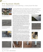
Figure 1: Collage of some structural and geotechnical failures and damages observed at utility scale ground mount solar farms
Figure 2: Heavy damage to structural system and foundations due to high wind load at a utility scale ground mount solar farm [Picture embossed to protect source]
Figure 3: Significant corrosion damage observed at a utility scale ground mount solar farm
Figure 4: Significant Snow Load Damage observed at a Utility Scale Ground Mount Solar Farm [Picture embossed to protect source]
Figure 5: Damage presumably due to Frost Heave
16
MARCH•APRIL2018 /// www.nacleanenergy.com
A scarcity of good utility scale solar project sites, paired with insufficient engineering, can result in heavy financial losses. Ready-to-build sites with good soils are getting harder to come by; in order to take advantage of available farmland, brown fields, abandoned land, and waste deposits, structural and geotechnical engineers need to incorporate diligent, interdisciplinary, and hand-in-hand engineering.
A growing number of solar systems are built on challenging terrain, with di cult and inhomogeneous soil conditions or irregular topography. At the same time, the frequency of failures and damaged utility scale solar plants is rising (see Fig. 1). Regardless of the cause of the damage, there are solutions to help overcome these challenges, thereby safeguarding investments, and improving preparedness for future changes in the challenging environment.
Wind load is the most frequent source of failures, followed by snow load, then dead load combined with seismic loads. Figures 2 through 10 show examples of damage to utility-scale plants due to various failures. Note that
in Fig. 4, the snow load damage destroyed not only the mounting structure, but also nearly all of modules of this 5MWp farm. e wooden cable drum served as a temporary support after the damage had already occurred. Also note, as observed on Fig. 9, that dynamic loads can lead to compaction of insu ciently compacted ll soils. Additionally, many contractors may attempt to conceal issues faced during installation by installing wooden wedges - not a durable construction element. is particular weakness was exposed at many foundation points during a subsequent storm.
All of these images illustrate the large variety of reasons for severe damage or complete failure. In order to understand the nature of damages, and to avoid future capital loss, Fig. 11 categorizes the possible range of damages, and distinguishes between which a ect the mounting superstructure, the foundation, or both. Furthermore, installation damages are categorized.
Foundation is critical. Incorrect design can a ect the entire mounting system, including the PV modules.
e panel mounting system foundation links the solar equipment to the soil beneath the entire system (see Fig. 12). Recently, small steel piles of various con gurations have become the most common type of foundation method (see Fig. 13), if the subsurface conditions allow this application. is “mini pile foundation” has to safely transfer loads from snow, wind, dead, and seismic forces into the soil.
e resulting loads are minimal when compared to forces acting on large building structures. However, the load e ect of wind and gust activity is high compared to the dead load (weight) of a solar mounting system. Several thousand foundation elements are usually needed to build even a 10-megawatt utility scale ground mount PV system. Steel mini-piles have proven to be a very economic, quickly installable, and reliable foundation solution for small and large scale solar farms. In addition to a conventional subsurface investigation and numeric modelling, performing load tests at the site to simulate cyclic wind and snow loads, seasonal uctuations, and soil variability, provides an opportunity to both con rm the su ciency and optimize the steel mini-pile foundation design.
Figure 8: Change of soil consistency due to climatic impacts as a potential reason for pile failure
Figure 6: Example for significant differential settlement [Picture embossed to protect source]
Figure 7: Damaged pile foot due to ramming obstructions
Figure 9: Left hand side: Dynamic loads led to compaction of insufficiently compacted Cut & Fill; right hand side: Subcontractor tried to hide problems he faced during installation
