Page 30 - North American Clean Energy March April 2015
P. 30
solar energy
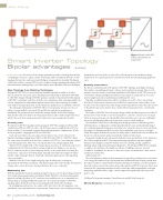
Figure 1. Bipolar ±1000 VDC
Smart Inverter Topology
enables reduced home run
requirements
Bipolar advantages
By Jeff Harrell
the inverter is in a unique position to provide technology that unlocks foundations, and crane picks, are also reduced. Furthermore, fewer medium-voltage
IN ANY PV SYSTEM,
compelling per-formance enhancements and savings. his isn’t only based on the overall transformers are required, given less array blocks overall, thereby optimizing equipment
topology, but also the coordi-nated and intelligent component functionality. he bipolar costs.
±1000 volts of direct-current (VDC) inverter enables a unique topology with advanced DC-
side innovations, making utility-scale solar simpler, more afordable, and more intelligent.
Enabling innovations
he inverter is fundamental to the bipolar ±1000 VDC topology, providing technology
New Topology from Existing Technology
that enables com-pelling performance enhancements and system savings. However, the
Monopolar 1000 VDC is a current industry standard topology for utility-scale solar integral, contactor-based recom-bining capabilities of the bipolar ±1000 VDC inverter go
projects. However, discussion and technology has already begun to shift from 1000 VDC even further, ofering intelligent performance that enhances energy harvest, increases
to 1500 VDC designs. hough 1500 VDC promises a number of potential beneits, bipolar system insight and control, and minimizes additional DC costs.
±1000 VDC technology can deliver all of the same advantages, while remaining within the Typically, an additional and external DC recombiner is used to collect current from
current equipment set with familiar implementation. Plus, this technology is available all of the PV sub-arrays in a plant to meet NEC 2011 requirements, and to utilize circuit
now, with no waiting required for new development, qualiication, or standards evolution.
breaker or fuse-based protection. his design results in paralleled circuits when the inverter
he advantages that bipolar ±1000 VDC ofers over monopolar systems are reduced is of, and the same protection levels are uti-lized for forward and reverse current-fault
balance-of-system (BoS) costs on the DC and AC side, and on the overall project conditions.
installation. Two primary factors enable this savings: bipolar ±1000 VDC topology he bipolar ±1000 VDC inverter’s unique design enables intelligent protection of the DC
dramatically reduces DC home-run wiring requirements, and it enables larger block sizes, system in the event of fault. A current-sensing device controls a contactor on each input,
which reduces AC wire requirements and construction costs, among other beneits.
which opens based on sepa-rate thresholds for forward and reverse current, enabling the
inverter to intelligently isolate sub-arrays in the event of a fault condition.
Crafting cuts
Given that the ±1000 VDC is a loating array during operation, it eliminates ground-
he bipolar ±1000 VDC topology enables pairing of 1000 VDC equipment with in-ield, fault blind spots, en-abling more reliable ground-fault detection and troubleshooting at
combiner-level PV ties (CPTs) to reduce the DC home-run wire length by up to 50%. As site commissioning and during oper-ation. Moreover, when the inverter isn’t in operation,
shown in Figure 1, in standard, neg-atively grounded monopolar conigurations, all sub- this approach eliminates paralleled circuits due to individual contactors on each input.
arrays are positive, ranging from 0 VDC to 1000 VDC.
Lastly, this approach allows the operator to safely isolate a faulted sub-array and allows the
Each sub-array requires its own, dedicated set of home-run circuits. However, the inverter to continue power production with the unafected sub-arrays.
bipolar technology, ranging from 0 VDC to 1000 VDC and 0 VDC to -1000 VDC, allows Integrated sensing doesn’t only provide fault protection and isolation; it also eliminates
the connection of neutrals in the ield via a combiner level PV tie, connecting two separate the need for supplemental DC sub-array monitoring, typically an expensive upgrade.
arrays during operation. his reduces overall, DC home-run wiring length by half.
Unique system insight is availa-ble with the inverter’s existing sensing capabilities,
Shorter DC wire length reduces the voltage drop across these circuits by the same factor, allowing enhanced plant monitoring and diagnostics. he integrated NEC 2011 complaint
resulting in lower DC line loss and increasing energy harvest. Engineers can also size
recombiner also eliminates the signiicant expense of adding a sepa-rate external
the DC conductors to the re-quired ampacity for the circuit, rather than over-sizing the recombiner. In addition, the inverter’s contactors require less maintenance than conven-
conductor to compensate for voltage drops. Typically, this allows the designer to utilize tional fuses and breakers.
smaller conductor gauges than in comparable monopolar applications, reducing wiring Addressing needs
costs even further.
he solar industry is unique in that innovation is spurred by an imperative need to drive
With the reduced DC wire length and gauge, typical utility project savings are clean energy alternatives to price parity with more traditional forms of power production.
approximately $10,000 per megawatt, with typical single-axis tracker designs. Even greater he urgency of this need has motivated rapid technological evolution, as well as uniquely
savings can be achieved in more elon-gated layouts due to site constraints.
innovative advancements. he innova-tions of the bipolar ±1000 VDC inverter ofer a step
forward in the continuing evolution of solar technol-ogy, addressing multiple needs and
Maximizing size
integrating capabilities into a single, central component, signiicantly reducing overall
With the optimized DC system topology, designers may increase the generating array block project costs.
size, maxim-izing energy yield per installation dollar. With the conventional monopolar
approach on larger block siz-es, DC conductor sizes would increase to accommodate for Jef Harrell is the product manager, Central Inverters with AE Solar Energy, Inc.
voltage drop, becoming prohibitively expen-sive. In contrast, the bipolar ±1000 VDC
topology allows for block sizes that are unattainable with stand-ard technology.
AE Solar Energy, Inc. | www.advanced-energy.com
By enabling larger block sizes, the enhanced DC side reduces the AC equipment costs,
installation costs, and maintenance requirements. Construction costs, including trenching,
30 nacleanenergy.com
MARCH/APRIL 2015