Page 40 - North American Clean Energy July August 2015
P. 40
wind power
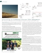
Figure 1 Figure 2
Figure 3 Figure 4
Improving on Collector Circuit TOV Mitigation
By using combined circuit breakers & grounding switches
by C. M. Ober
TEMPORARY OVERVOLTAGE (TOV) poses a serious hazard to equipment connected to a power tral shift will occur as the substation breaker is tripped in response to the fault. While the
grid. TOV can occur during a ground fault such as a tree limb falling on a power line. here wind turbine generators continue to operate the feeder becomes isolated without a ground
are situations that can occur in wind plants that produce far more severe TOV than is nor- source but with one phase connected to ground. As a result, the phase-to-phase voltage is
mally encountered in typical MV utility distribution systems. hese TOVs are a critical fac- maintained even when one of the phases is at zero potential to ground. For the unfaulted
tor in wind plant insulation coordination.
phases, the phase-to ground voltage and therefore the phase-to-neutral voltage can be the
same value as the phase-to-phase voltage. In other words the unfaulted phase voltages will
Ground faults and loss of ground reference
rise greatly, typically to 1.73 times pre-fault voltage or more as shown in (Figure 1).
In a three-phase efectively grounded system, a ground fault on one phase will cause the he probability that the wind turbines will not trip in response to the fault, but keep op-
un-faulted phases voltage to rise if the X0/X1 ratio at the fault location is greater than one. erating, is greatly enhanced by low-voltage ride through (LVRT) compliance requirements
Typical practice is to provide efective grounding (X0/X1 < +3) within the collector system. that have been imposed on wind plants by grid operators. In fact the actual TOV can be sig-
In most cases, neither wind turbine generators, nor the GSU transformers, provide neutral niicantly more severe than the 173% value, due to the capacitance of the isolated feeder.
grounding for the wind plant MV system. he normal source of grounding for the collector he “ungrounded” feeder is not actually ungrounded, but is grounded via the capacitance
feeders is from the wind plant substation. If a ground fault should happen, a derived neu-
of the feeder cables. he negative reactance of the capacitance results in a negative X0/X1
ratio, which will further increase unfaulted phase voltage. Another consequence of the “ca-
pacitive grounding” of a nominally ungrounded feeder is the fact that the fault arc can clear
itself, due to the very low fault current present once the feeder is isolated (some turbines
might not trip on the fault), and then restrike. he restrike triggers a voltage oscillation
and the arc may again interrupt at a current zero, trapping an even higher voltage. his
process can repeat, escalating the voltage to higher levels.
TOV mitigation
To avoid these TOVs, dedicated grounding transformers on each feeder (Figure 2) have
become a common practice for wind farm collection circuit design. his eliminates the pos-
sibility of ungrounded operation due to feeder isolation.
he sizing of the grounding transformers must consider the rating of the wind turbine
generators (WTGs) connected to the feeder, the WTG characteristics, and the amount of
cable charging capacitance. In some cases, the WTG behavior for such a feeder isolation
condition is complex enough to preclude simple calculation of grounding transformer im-
pedance requirements. In such a case, detailed simulations are necessary. Without ground-
ing reference, overvoltage can damage collector system cables, arrestors, and the wind
turbine transformer. But, installing a grounding transformer on every feeder will increase
equipment, labor, engineering, and installation costs, as well as the substation’s footprint.
Improving TOV mitigation
here is an improved alternate method to provide proper ground reference to a wind col-
lector feeder not having to add a grounding transformer. It is to replace the substation vac-
uum circuit breaker with a combined vacuum circuit breaker and mechanically interlocked
grounding switch (Figure 3). In essence, a high speed, triple-pole, double-throw switch
with a very fast commutation time. he combined vacuum circuit breaker and mechani-
cally interlocked grounding switch is a unique piece of equipment, especially designed for
renewable energy collection circuit application. Once the collector circuit breaker opens on
a single-phase-to-ground fault and the arc has been cleared, the mechanically interlocked
grounding switch will close clamping all three phases to ground. As a result all WTGs will
40 JULY/AUGUST 2015
nacleanenergy.com