


Solar Thermal Technology: Simplifying designs for US market infiltration


 In recent years, a steady growth of the market for solar thermal heating technology has brought about a large number of system installations across the globe. However, in North America, solar thermal systems are still quite complex in terms of installation and operation. And, despite an excellent and stable subsidy scheme—offsetting 50% to 75% of system costs—solar thermal technology is losing out to the popularity of low-cost photovoltaic’s (PVs).
It’s clear that a more simplified system design is required, allowing for a “set and forget” installation, if solar thermal is ever truly going to join the US renewables’ revolution.
Performance flaws
Stagnation on a solar thermal installation is one of the most frequently discussed problems when addressing the performance of solar thermal flat-plate collectors. When the heat transfer liquid is exposed to temperatures above 220° C (430° F), rapid degradation of the anti-freeze that’s used in most systems is the result. Unfortunately, this can lead to damage and eventual failure of the solar circuit.
Overheating is also a serious concern, resulting from the vapor formed during stagnation. If it penetrates into the liquid circuit, it can damage and destroy components, such as the vents, valves, membrane expansion vessels, and more. The solar liquid inside the collector will begin to evaporate when the circulation of the heat transfer liquid is stopped, and the excess solar heat of the collector can’t be dissipated any more. This can happen when heat storage capacity is exceeded and solar loading continues (i.e. during summer time, especially in space heating supporting installations or in southern latitudes, when heat demand is lower than the amount of solar heat delivered).
Yet another common reason for failure of the power supply can occur if the circulation pump stops working for any reason. The heat dissipation power of the circuit depends on the heat losses of the tubing. Therefore, it might be necessary to add a heat dissipation vessel upstream of the expansion vessel as an extra heat dissipation device. This vessel serves to protect the expansion vessel, and the other components of the solar pumping group, against intolerably high temperatures by dissipating the heat of the condensing vapor.
The quantity of vapor formation in the collector can be described by the maximum vapor production power. Some existing data shows values from 15 W/m² for serpentines up to 385 W/m² at 4-bar relative pressure for vacuum tubes. The maximum penetration depth of vapor into the solar circuit can be estimated if the heat losses per length of piping, and the heat dissipation performance of a (potentially) mounted heat dissipation vessel upstream of the expansion vessel, are known. The maximum penetration depth of the vapor is reached when the maximum vapor production power equates to the heat losses of the tube, and the heat dissipation performance of the heat dissipation vessel.
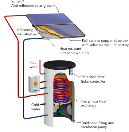
Consequently, careful design of the piping and heat dissipation vessel guarantees sufficient control of the vapor penetration into the piping. To meet this demand, at least one system currently on the market offers an intrinsic fail-proof safety mechanism against overheating by utilizing a self-draining effect during stagnation (see image).
Herein, the solar circuit is only partly filled with heat transfer liquid, while the remainder of the piping and the collector stay air-filled. If the temperature in the collector reaches a certain level, the pump starts pushing the liquid upstream. This movement of liquid displaces the air into a collecting vessel, and the liquid begins to circulate. When the pump stops, the liquid naturally drains back into the collecting vessel via gravity, and the air moves back into the collector. As a result, the heat transfer liquid is removed from exposure to solar heat during stagnation of the solar circuit, avoiding any thermal degradation.
To avoid the anti-freeze degradation problem, some drain-back systems operate with pure water. This is only acceptable if it can be fully assured that the water in the solar circuit will never be exposed to freezing conditions. However, experience shows that in Europe, or even in northern Africa and the Middle East, this can rarely be absolutely guaranteed. Optimal frost protection, therefore, is only provided with anti-freeze.
Installation simplicity
Solar thermal system installation and set-up errors often go unnoticed until it’s too late. Only qualified plumbers are able to ensure the high level of accuracy necessary for the installation of today’s complex solar thermal systems. Unfortunately, a large number of non-specialized plumbers carry out an increasing number of solar thermal installations. One solution to this challenge is to radically reduce the complexity of the installation process.
Recently, one research and development (R&D) team carried out an integrated systems analysis with the goal of removing any device not absolutely necessary, integrating all functional components in the most compact manner possible. A solar tank development was the result, with the inclusion of intrinsically safe heat exchanger technology to avoid overheating.
Findings & analysis
Drain-back systems don’t need any heat traps because thermo-siphon effects cannot occur. Insufficient deaeration, which occurs sometimes in installations, isn’t an issue with drain-back systems. Air vents also aren’t necessary. The occasionally failing membrane expansion vessels aren’t required, since the collecting vessel or the only partially filled storage tank compensate for the thermal expansion of water.
An increased heat transfer rate inside the heat exchanger coil provided a positive side effect of integrating the collecting vessel. During operation, there was a two-phase flow inside the coil. The liquid moved rapidly and turbulently along the inside surface of the coil, forming a thin layer. This is actually highly preferable for the heat transfer when compared to the relatively slow, near-laminar flow of the liquid when the coil is completely filled, as the inner-mass of the liquid contributes very little to the heat transfer.
In the end, a high level of pre-assembly, along with the reduction of the number of required components, led to a significant reduction of installation time. Steps that related to the pumping group, membrane expansion vessel, and solar controller became completely obsolete. All these components are either pre-assembled on a hybrid system, or not required at all.
Solar thermal commercialization
For solar thermal technology to survive in the US solar boom, systems should become mainstream for new construction and retrofits. In countries such as Turkey, Greece, and Cypress, for example, solar thermal installations are standard—generating between 50% and 100% of the domestic hot water (DHW) needs in households by keeping the technology simplified.
Ideally, self-draining systems should be the system of choice. Simplified systems that don’t require more than 12 to 14 man-hours would not only help with installation errors, but would also help cut overall system costs by $6,000 to $7,000, even before the rebates and incentives kick in.
Lastly, design and system component integration should be at the responsibility of the manufacturer. Only system with an OG-300 label should be allowed to receive incentives and subsidies, thereby reducing system design errors and flaws with custom and integrated solar thermal installations.
Joerg Gaebler is managing director of Wagner Solar Inc. in Boston, Massachusetts, a 100% subsidiary of Wagner & CO, Germany.
Wagner & Co is a one-stop total systems provider in the field of solar thermal solutions and systems integrator for solar power installations of any scale—from small, off-grid solutions to large-scale PV power plants. In May of 2010, Wagner & Co founded the Wagner Solar Inc. to develop the North American Market.
Wagner Solar Inc.
www.usa.wagner-solar.com
Author: Joerg Gaebler
Volume: September/October 2014

.jpg?r=8269)
.gif?r=5158)
.jpg?r=4926)